Spine


Spine


Fractures of the vertebral column are important not only because of the structures involved but also because of the complications that may arise affecting the spinal cord. Constituting approximately 3% to 6% of all skeletal injuries, fractures of the vertebral column are most commonly encountered in people between the ages of 20 and 50 years, with the majority of cases (80%) being seen in males. Most spinal fractures occur at the thoracic and lumbar levels, but injury to the cervical area has a greater potential risk for spinal cord damage. Automobile accidents, sports-related activities (e.g., diving, skiing), and falls from heights are usually the circumstances in which spinal injuries are sustained.

The spine is composed of 33 vertebrae: 7 cervical, 12 thoracic, 5 lumbar, a sacrum of 5 fused segments, and a coccyx of 4 fused segments. With the exception of the first and second cervical vertebrae (C1 and C2), the vertebral bodies are separated from each other by intervertebral disks.


Cervical Spine


Anatomic-Radiologic Considerations

Structurally, the first and second cervical vertebrae possess anatomic features distinct from those of the remaining five cervical vertebrae (Fig. 11.1). The first cervical vertebra, C1 or atlas, is an osseous ring consisting of anterior and posterior arches connected by two lateral masses. The atlas has no body; its main structures are the lateral masses, also called articular pillars. The second vertebra, C2 or axis, is a more complex structure whose distinguishing feature is the odontoid process, also known as the dens (tooth), projecting cephalad from the anterior surface of the body. The space between the odontoid process and the anterior arch of the atlas, called the atlantal-dens interval, should not exceed 3 mm in adults, whether the head is flexed or extended. In children younger than age 8 years, this distance has been reported to be as much as 4 mm, particularly in flexion, secondary to greater ligamentous laxity.

The vertebrae C3-7 exhibit identical anatomic features and are more uniform in appearance, consisting of a vertebral body and a posterior neural arch, including the right and left pedicles and laminae, which together with the posterior aspect of the body enclose the spinal canal (Fig. 11.2). Extending caudad and cephalad from the junction of the pedicle and lamina on each side are superior and inferior articular processes, which form the apophyseal joints between the successive vertebrae. Extending laterally from the pedicle on each side is a transverse process and, in the posterior portion, a spinous process extends from the junction of the laminae in the midline. The vertebra C7, in addition, is distinguished by its long spinous process and large transverse processes.

Radiographic examination of a patient with cervical spine trauma may be difficult and is usually limited to one or two projections; because frequently the patient is unconscious, there are associated injuries and unnecessary movement risks damage to the cervical cord. The single most valuable projection in these instances is the lateral view, which may be obtained in the standard fashion or with the patient supine, depending on the condition (Fig. 11.3). This projection suffices to demonstrate most traumatic conditions of the cervical spine, including injuries involving the anterior and posterior arches of C1; the odontoid process, which is seen in profile; and the anterior atlantal-dens interval. The bodies and spinous processes of C2-7 are fully visualized, and the intervertebral disk spaces and prevertebral soft tissues can be adequately evaluated. The lateral radiograph may also be obtained in flexion of the neck, which is particularly effective in demonstrating suspected instability at C1-2 by allowing evaluation of the atlanto-odontoid distance; an increase in this distance to more than 3 mm indicates atlantoaxial subluxation. It is of the utmost importance on the lateral projection of the cervical spine that the C7 vertebra be visualized because this is the most commonly overlooked site of injuries.

The lateral view of the cervical spine, including the lower part of the skull, is extremely important to evaluate the vertical subluxation involving the atlantoaxial articulation and the migration of the odontoid process into the foramen magnum. Several measurements are helpful to determine atlantoaxial impaction or cranial settling resulting in superior migration of the odontoid process (Figs. 11.4, 11.5, 11.6, 11.7).

On the anteroposterior radiograph of the cervical spine (Fig. 11.8), the bodies of the C3-7 vertebrae (and occasionally in young persons, even the C1 and C2 vertebrae) are well demonstrated, as are the uncovertebral (Luschka) joints and the intervertebral disk spaces. The spinous processes are seen almost on end, casting oval shadows resembling teardrops. A variant of the anteroposterior projection known as the open-mouth view (Fig. 11.9) may also be obtained as part of the standard examination. This view provides effective visualization of the structures of the first two cervical vertebrae. The body of C2 is clearly imaged, as are the atlantoaxial joints, the odontoid process, and the lateral spaces between the odontoid process and the articular pillars of C1. If the open-mouth view is difficult to obtain or the odontoid process is not clearly visualized, particularly its upper half, then the Fuchs view may be helpful (Fig. 11.10). Oblique projections of the cervical spine (Fig. 11.11) are not routinely obtained, although at times they help visualize obscure fractures of the neural arch and abnormalities of the neural foramina and apophyseal joints. Special projections may occasionally be required for sufficient evaluation of the structures of the cervical spine. The pillar view (Fig. 11.12), which may be obtained in the anteroposterior or oblique projection, serves to demonstrate the lateral masses of the cervical vertebrae, and the swimmer’s view (Fig. 11.13) may be used for better demonstration of the C7, T1, and T2 vertebrae, which on the standard lateral or oblique projection are obscured by the overlapping clavicle and soft tissues of the shoulder girdle. Fluoroscopy and videotaping are usually of little help in acute injuries because pain may prevent the necessary movement for positioning.


FIGURE 11.1 Topographic anatomy of the C1 and C2 vertebrae.


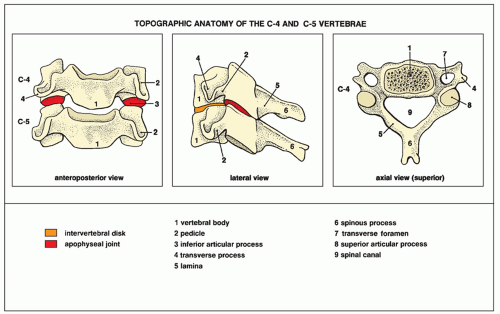
FIGURE 11.2 Topographic anatomy of the C4 and C5 vertebrae, representing the midcervical and lower cervical vertebrae.


FIGURE 11.3 Lateral view. (A) For the erect lateral view of the cervical spine, the patient is standing or seated, with the head straight in the neutral position. The central beam (red broken line) is directed horizontally to the center of the C4 vertebra (at the level of the chin). (B) For the cross-table lateral view, the patient is supine on the radiographic table. The radiographic cassette (a grid cassette to obtain a clearer image) is adjusted to the side of the neck, and the central beam is directed horizontally to a point (red dot) approximately 2.5 to 3 cm caudal to the mastoid tip. (C) The radiograph in this projection clearly shows the vertebral bodies, apophyseal (facet) joints, spinous processes, and intervertebral disk spaces. It is mandatory to demonstrate the C7 vertebra. (Continued)


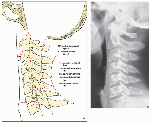
FIGURE 11.3 Lateral view. Continued (D) With this view, the five contour lines of the normal cervical spine can be demonstrated: anterior vertebral line drawn along anterior margins of the vertebral bodies; posterior vertebral line (outlines anterior margin of spinal canal), drawn along posterior margins of the vertebral bodies; spinolaminar line (outlines posterior margin of the spinal canal), drawn along the anterior margins of the bases of the spinous processes at the junction with lamina; posterior spinous line drawn along the tips of the spinous processes from C2-7, which should be running smoothly, without angulation or interruption; and the clivus-odontoid line, drawn from the dorsum sellae along the clivus to the anterior margin of the foramen magnum should point to the tip of the odontoid process at the junction of the anterior and middle thirds. The retropharyngeal space (distance from the posterior pharyngeal wall to the anteroinferior aspect of C2) should measure 7 mm or less; the retrotracheal space (distance from the posterior wall of the trachea to the anteroinferior aspect of C6) should measure no more than 22 mm in adults and 14 mm in children. (E) Radiograph obtained with low-kilovoltage technique demonstrates prevertebral soft tissues to better advantage.


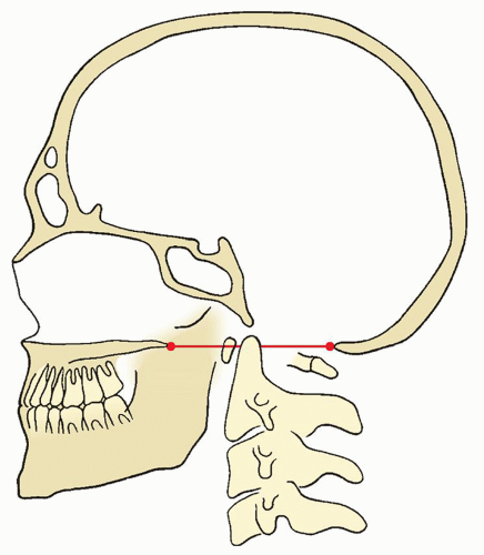
FIGURE 11.4 The Chamberlain line. This line is drawn from the posterior margin of the foramen magnum (opisthion) to the dorsal (posterior) margin of the hard palate. The odontoid process should not project above this line more than 3 mm; a projection of 6.6 mm (±2 standard deviation [SD]) above this line strongly indicates cranial settling.


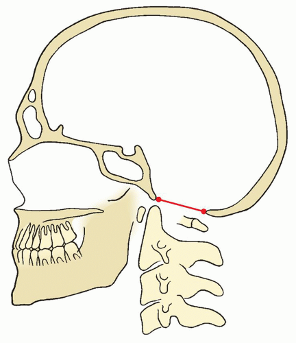
FIGURE 11.5 The McRae line. This line defines the opening of the foramen magnum and connects the anterior margin (basion) with posterior margin (opisthion) of the foramen magnum. The odontoid process should be just below this line or the line may intersect only at the tip of the odontoid process. In addition, a perpendicular line drawn from the apex of the odontoid to this line should intersect it in its ventral quarter.


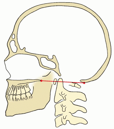
FIGURE 11.6 The McGregor line. This line connects the posterosuperior margin of the hard palate to the most caudal part of the occipital curve of the skull. The tip of the odontoid normally does not extend more than 4.5 mm above the line.


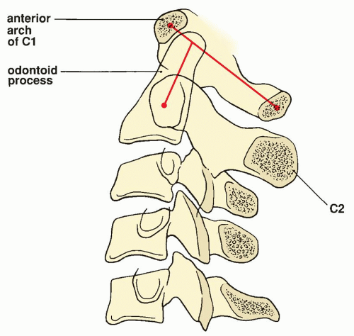
FIGURE 11.7 Ranawat method. Ranawat and associates developed a method for determining the extent of the superior margin of the odontoid process, since the hard palate often is not identifiable on radiographs of the cervical spine. The coronal axis of C1 is determined by connecting the center of the anterior arch of the first cervical vertebra with its posterior ring. The center of the sclerotic ring in C2, representing the pedicles, is marked. The line is drawn along the axis of the odontoid process to the first line. The normal distance between C1 and C2 in men averages 17 mm (±2 mm SD), and in women, 15 mm (±2 mm SD). A decrease in this distance indicates cephalad migration of C2.


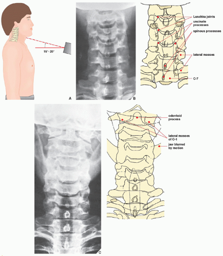
FIGURE 11.8 Anteroposterior view. (A) For the anteroposterior view of the cervical spine, the patient is either erect or supine. The central beam is directed toward the C4 vertebra (at the point of the Adam’s apple) at an angle of 15 to 20 degrees cephalad. (B) The radiograph in this projection demonstrates the C3-7 vertebral bodies and the intervertebral disk spaces. The spinous processes are seen superimposed on the bodies, resembling teardrops. The C1 and C2 vertebrae are not adequately seen. For their visualization, the patient is instructed to open and close the mouth rapidly. Motion of the mandible blurs this structure, and C1 and C2 become visible (C).


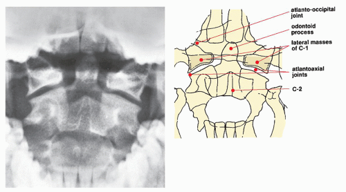
FIGURE 11.9 Open-mouth view. For the open-mouth view, the patient is positioned in the same manner as for the supine anteroposterior projection; the head is straight, in the neutral position. With the patient’s mouth open as widely as possible, the central beam is directed perpendicular to the midpoint of the open mouth. During the exposure, the patient should softly phonate “ah” to affix the tongue to the floor of the mouth so that its shadow is not projected over C1 and C2. On the radiograph obtained in this projection, the odontoid process, the body of C2, and the lateral masses of the atlas are well demonstrated; the atlantoaxial joints are seen to best advantage.


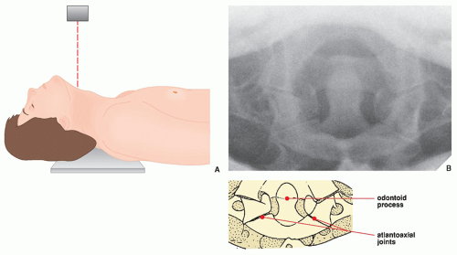
FIGURE 11.10 Fuchs view. (A) For the Fuchs views of the odontoid process, the patient is supine on the table, with the neck hyperextended. The central beam is directed vertically to the neck just below the tip of the chin. (B) On the radiograph obtained in this projection, the odontoid, especially its upper half, is clearly visualized.


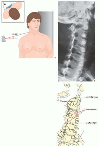
FIGURE 11.11 Oblique view. (A) An oblique view of the cervical spine may be obtained in the anteroposterior (as shown here) or posteroanterior projection. The patient may be erect or recumbent, but the erect position (seated or standing) is more comfortable. The patient is rotated 45 degrees to one side—to the left, as shown here, to demonstrate the right-sided neural foramina and to the right to demonstrate the left-sided neural foramina. The central beam is directed to the C4 vertebra with 15- to 20-degree cephalad angulation. (B) The radiograph obtained in this projection is effective primarily for demonstrating the intervertebral neural foramina.


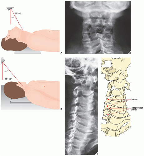
FIGURE 11.12 Pillar view. (A) For the pillar view of the cervical spine, the patient is supine on the table, with the neck hyperextended. The central beam is directed to the center of the neck in the region of the thyroid cartilage at a caudal angulation of 30 to 35 degrees. (B) On the radiograph obtained in this projection, the lateral masses (pillars) of the cervical vertebrae are well demonstrated. (C) The pillar view can also be obtained in the oblique projection. The patient is supine on the table, with the neck hyperextended and the head rotated 45 degrees toward the unaffected side. The central beam is directed with about 35- to 40-degree caudal angulation to the lateral side of the neck about 3 cm below the earlobe. (D) On the radiograph obtained with leftward rotation of the head, an oblique view of the right pillars is achieved.


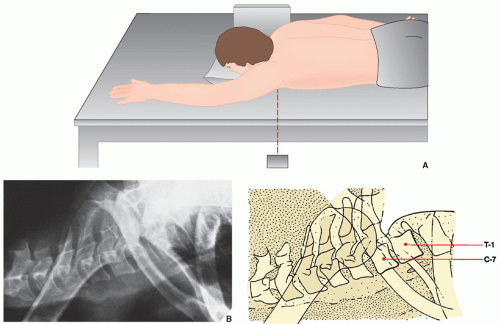
FIGURE 11.13 Swimmer’s view. (A) For the swimmer’s view of the cervical spine, the patient is placed prone on the table with the left arm abducted 180 degrees and the right arm by the side, as if swimming the crawl. The central beam is directed horizontally toward the left axilla. The radiographic cassette is against the right side of the neck, as for the standard cross-table lateral view. (B) The radiograph obtained in this projection provides adequate visualization of the C7, T1, and T2 vertebrae, which would otherwise be obscured by the shoulders.

In order to not overlook an abnormality during evaluation of the conventional radiographs of the cervical spine, systematic approach to the imaging study is of paramount importance. “JOB LIST” such as provided in Figure 11.14 may be of help to methodically analyze the various anatomic structures.

Ancillary imaging techniques play an important role in the evaluation of suspected spinal trauma. Computed tomography (CT) is commonly used modality (Fig. 11.15). In the evaluation of fractures of the odontoid process, for example, CT is particularly helpful. In determining the extent of cervical spine injuries in general, including soft-tissue trauma, this technique provides valuable information regarding the integrity of the spinal canal and the localization of fracture fragments within the canal.

Magnetic resonance imaging (MRI) has become the most effective modality to evaluate vertebral trauma because of the impressive quality of its images and its multiplanar capabilities, which allow the examination of acutely traumatized patients without moving them. In evaluating fractures, MRI is useful not only to determine the relationship of bony fragments that may be displaced in the vertebral canal but also to demonstrate the full extent of injury, especially to the soft tissues and the spinal cord. The effect of the trauma on the spinal cord can be directly imaged, and spinal cord compression can be diagnosed. The superior soft-tissue contrast resolution of MRI can reveal even minimal edema and small quantities of hemorrhage within the spinal cord. Injury to ligamentous structures and extradural pathology also may be readily identified. In the cervical spine, 3-mm-thick sagittal sections and 5-mm-thick axial sections are routinely obtained. The most effective are spin echo T1- and T2- or T2*-weighted images obtained in the sagittal plane. Sagittal MR images permit the evaluation of vertebral body alignment and integrity, along with the size of the spinal canal (Fig. 11.16A). On the parasagittal section, the articular facets are well demonstrated (Fig. 11.16B). More recently, fast scans (fast spin echo [FSE]) have been advocated for demonstrating injuries in the sagittal and axial planes. These fast gradient-echo pulse sequences have become a popular addition to, or a replacement for, spin echo T2-weighted sequences. Gradient-echo sequences have short acquisition times and adequate resolution and show a
satisfactory “myelographic effect” between cerebrospinal fluid and adjacent structures (Fig. 11.16C,D).


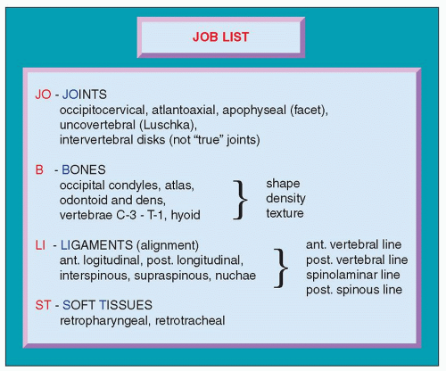
FIGURE 11.14 JOB LIST for evaluation of the cervical spine.


FIGURE 11.15 CT of the cervical spine. CT sections through the body of C6 (A), C7 (B), and the C6-7 intervertebral space (C) show the normal appearance of these structures.

On T1-weighted sagittal images of the cervical spine, the vertebral bodies that contain yellow (or fatty) marrow are imaged as high-signal intensity structures (see Fig. 11.16A). The intervertebral disks and the cord demonstrate intermediate signal intensity, while cerebrospinal fluid demonstrates low signal intensity.

On T2-weighted sagittal images, the vertebral bodies are imaged with low signal intensity, the intervertebral disks and cerebrospinal fluid demonstrate high signal intensity, and the cord demonstrates intermediate-to-low signal intensity.

On the axial images obtained in T1 weighting, the disk demonstrates intermediate signal intensity, the spinal fluid has low signal intensity, and the cord has high-to-intermediate signal intensity. On the axial images obtained in T2* weighting, multiplanar gradient recalled (MPGR), the disk is of high signal intensity and the spinal fluid is also of high signal intensity, in contrast to the spinal cord, which images as an intermediate-signal intensity structure. The bone demonstrates low signal intensity (see Fig. 11.16C,D).

In addition to its imaging capabilities, MR also has, according to some investigators, a prognostic value when attempting to predict the degree of neurologic recovery following trauma.

It has to be stressed, however, that CT alone or combined with myelography remains the better choice for evaluating vertebral fractures, especially when they are nondisplaced or involve the posterior elements (lateral masses, facets, laminae, spinous processes), largely because of the limitations of spatial resolution of MRI. In addition, imaging the acutely injured patient is difficult. The patient may be unstable or immobilized with either a halo or traction device unsuitable for the magnetic environment. For this reason, radiographs, CT, and myelography continue to play a significant role in the evaluation of the acutely traumatized spine. However, as Hyman and Gorey noted, chronic injury to the spinal cord is most accurately evaluated with MRI.

Since the advent of CT and MRI, myelography alone (Fig. 11.17A-C) is now rarely indicated in the evaluation of cervical injuries; if needed, this examination is usually performed in conjunction with CT (Fig. 11.17D).

For a summary of the preceding discussion in tabular form, see Tables 11.1, 11.2, 11.3.


Injury to the Cervical Spine

Traumatic conditions involving the cervical spine are almost always the result of indirect stress forces acting on the head and neck, the position of which at the time of impact determines the site and type of damage. As Daffner stressed, vertebral fractures occur in predictable and reproducible patterns that are related to the type of force applied to the vertebral column. The same force applied to the cervical, thoracic, or lumbar spine will result in injuries that appear quite similar, producing a pattern of recognizable signs that span the spectrum from mild soft-tissue damage to severe skeletal and ligamentous disruption. Daffner termed these patterns fingerprints of spinal injury; they depend on the mechanism of injury, which may be an excessive movement in any direction: flexion, extension, rotation, vertical compression, shearing, distraction—or a combination of these.

Of the greatest initial importance in suspected cervical injuries, however, is the question of stability of a fracture or dislocation (Table 11.4). Stability of the vertebral column depends on the integrity of the major skeletal components, the intervertebral disks, the apophyseal joints, and the ligamentous structures. One of the most important factors is the integrity of the ligaments of the spine: the supraspinous and interspinous ligaments, the posterior longitudinal ligament, and the ligamenta flava, which together with the capsule of the apophyseal joints constitute the so-called posterior ligament complex of Holdsworth (Fig. 11.18). Injuries are stable by virtue of intact ligamentous structures; the more severe the damage to these structures, the more liable they are to further displacement, with greater risk of sequelae involving the spinal cord. Radiographic findings that indicate instability, according to Daffner, are displacement of vertebrae, widening of the interspinous or interlaminar spaces, widening of the apophyseal joints, widening and elongation of the vertebral canal manifesting as widening of the interpedicular distance in transverse and vertical planes, and disruption of the posterior vertebral body line. Only one of these features needs to be present to make a radiographic assumption of an unstable injury. These remarks on stability also apply to injuries of the thoracic and lumbar segments.

Recently, Daffner and colleagues modified the classification of cervical vertebral injuries on the basis of CT findings, introducing “major” injuries


and “minor” injuries. The former are defined as having either radiographic or CT evidence of instability, with or without associated localized or central neurologic findings. The latter injuries have no radiographic or CT evidence of instability and do not produce or have no potential to cause neurologic findings. According to these authors, cervical injury should be classified as major if the following radiographic and CT criteria are present: displacement of more than 2 mm in any plane, widening of the vertebral body in any plane, widening of the interspinous or interlaminar space, widening of the facet joints, disruption of the posterior vertebral body line, widening of the disk space, vertebral burst, locked or perched facets either unilateral or bilateral, “hanged man” fracture of C2, fracture of the odontoid process, and type III occipital condyle fracture. All other types of fractures are considered to be minor.


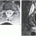
FIGURE 11.16 MRI of normal cervical spine. (A) T1-weighted spin echo sagittal midline section demonstrates anatomic details of the bones and soft tissues. The craniocervical junction is well outlined. The foramen magnum is defined by the fat within the occipital bone and clivus. The anterior and posterior arches of C1 appear as small oval marrow-containing structures at the upper cervical spine. The spinal cord is of an intermediate signal intensity outlined by lower signal of cerebrospinal fluid. The intervertebral disks are imaged with low signal intensity. (B) Parasagittal T2-weighted section demonstrates the apophyseal joints. (C) Short time inversion recovery (STIR) sagittal image shows vertebral bodies and spinous processes to be of low signal intensity. The high water content of the intervertebral disks produces a very high signal similar to that of cerebrospinal fluid. The cord is imaged as an intermediate-signal intensity structure. (D) Axial gradient recalled echo (GRE) section demonstrates neural foramina and nerve roots. The cervical cord is well outlined.


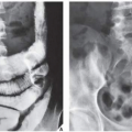
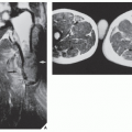
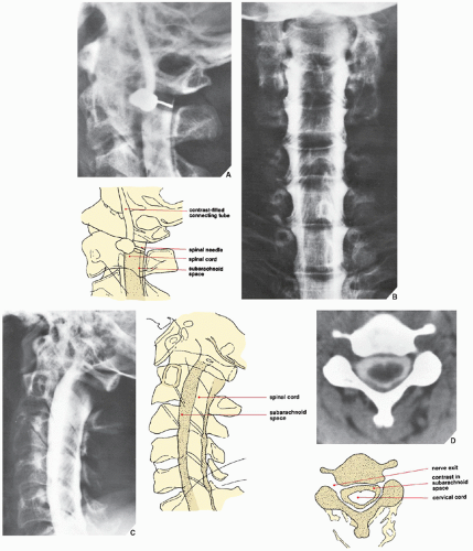
FIGURE 11.17 Myelography of the cervical spine. For myelographic examination of the cervical spine, the patient is recumbent on the table, lying on the left side. Using fluoroscopy, the point of entrance of the needle is marked at the C1-2 level, and a 22-gauge needle is inserted vertically, the tip being directed to the dorsal aspect of the subarachnoid space, above the lamina of C2. Free flow of spinal fluid indicates the correct position of the needle. (A) Approximately 10 mL of iohexol or iopamidol, watersoluble nonionic iodinated contrast agents, at a concentration of 240 mg iodine per mL, is slowly injected. Radiographs are obtained in the posteroanterior (B), cross-table lateral (C), and oblique projections. (Oblique projections, however, are obtained not by rotating the patient but by angling the radiographic tube 45 degrees.) If the lower segment of the cervical spine is not satisfactorily demonstrated or if the upper thoracic segment needs to be visualized, a radiograph may also be obtained in the swimmer’s position. Myelography demonstrates the thecal sac filled with contrast and the outline of the normal nerve roots and nerve root sleeves. (D) CT section at the level C3-4 obtained following myelography demonstrates the normal appearance of contrast in the subarachnoid space.


TABLE 11.1 Tissue Magnetic Resonance Imaging Signal Characteristics


Signal Intensity


T1 Weighting


T2 Weighting


Gradient Echo (T2*)


Low signal


Cortical bone


Vertebral end plates


Degenerated disks


Osteophytes


Spinal vessels


Cerebrospinal fluid


Cortical bone


Vertebral end plates


Ligaments


Degenerated disks


Osteophytes


Spinal vessels


Nerve roots


Bone marrow


Vertebral bodies


Vertebral end plates


Ligaments


Osteophytes


Intermediate signal


Spinal cord


Paraspinal soft tissue


Intervertebral disks


Nerve roots


Osteophytes


Paraspinal soft tissue


Osteophytes


Spinal cord


Facet cartilage


Bone marrow


Vertebral bodies


Annulus fibrosus


Spinal cord


Nerve roots


High signal


Epidural venous plexus


Hyaline cartilage


Epidural and paraspinal fat


Bone marrow


Vertebral bodies


Intervertebral disks


Cerebrospinal fluid


Intervertebral disk


Cerebrospinal fluid


Facet cartilage


Epidural venous plexus


Arteries


Modified from Kaiser MC, Ramos L. MRI of the spine. A guide to clinical applications. Stuttgart: Thieme Verlag; 1990.


TABLE 11.2 Standard and Special Radiographic Projections for Evaluating Injury to the Cervical Spine


Projection


Demonstration


Anteroposterior


Fractures of the bodies of C3-7


Abnormalities of the


Intervertebral disk spaces


Uncovertebral (Luschka) joints


Open-mouth


Fractures of


Lateral masses of C1


Odontoid process


Body of C2


Jefferson fracture


Abnormalities of atlantoaxial joints


Fuchs


Fractures of odontoid process


Lateral


Occipitocervical dislocation


Fractures of


Anterior and posterior arches of C1


Odontoid process


Bodies of C2-7


Spinous processes


Hangman’s fracture


Burst fracture


Teardrop fracture


Clay shoveler’s fracture


Simple wedge (compression) fracture


Unilateral and bilateral locked facets


Abnormalities of


Intervertebral disk spaces


Prevertebral soft tissues


Atlanto-odontoid space


In flexion


Atlantoaxial subluxation


Oblique


Abnormalities of


Intervertebral (neural) foramina


Apophyseal (facet) joints


Pillar (anteroposterior or oblique)


Fractures of lateral masses (pillars)


Swimmer’s


Fractures of C7, T1, and T2


TABLE 11.3 Ancillary Imaging Techniques for Evaluating Injury to the Cervical, Thoracic, and Lumbar Spine


Technique


Demonstration


Tomography (almost completely replaced by CT)


Fractures, particularly of the odontoid process


Localization of displaced fracture fragments


Progress of treatment


Fracture healing


Status of spinal fusion


Myelography


Obstruction or compression of the dural (thecal) sac


Displacement or compression of the spinal cord


Abnormalities of


Spinal nerve root sleeves (sheaths)


Subarachnoid space


Herniated disk


Diskography


Limbus vertebra


Schmorl node


Herniated disk


CT (alone or combined with myelography and/or diskography)


Fractures of the occipital condyles


Abnormalities of


Lateral recesses and neural foramina Spinal cord


Complex fractures of the vertebrae


Localization of displaced fracture fragments in spinal canal


Spondylolysis


Disk herniation


Paraspinal soft-tissue injury (e.g., hematoma)


Progress of treatment


Fracture healing


Status of spinal fusion


Radionuclide imaging (scintigraphy, bone scan)


Subtle or obscure fractures


Recent versus old fractures


Fracture healing


MRI


Same as myelography and CT combined


Annular tears


TABLE 11.4 Classification of Injuries to the Cervical Spine by Mechanism of Injury and Stability


Condition


Stability


Flexion Injuries


Occipitocervical dislocation


Unstable


Subluxation


Stable


Dislocation in facet joints (locked facets)


Unilateral


Stable


Bilateral


Unstable


Odontoid fractures


Type I


Stable


Type II


Unstable


Type III


Stable


Wedge (compression) fracture


Stable


Clay shoveler’s fracture


Stable


Teardrop fracture


Unstable


Burst fracture


Stable or unstable


Extension Injuries


Occipitocervical dislocation


Unstable


Fracture of posterior arch of C1


Stable


Hangman’s fracture


Unstable


Extension teardrop fracture


Stable


Hyperextension fracture-dislocation


Unstable


Compression Injuries


Occipital condyle fracture (types I, II)


Stable


Jefferson fracture


Unstable


Burst fracture


Stable or unstable


Laminar fracture


Stable


Compression fracture


Stable


Shearing Injuries


Lateral vertebral compression


Stable


Lateral dislocation


Unstable


Transverse process fracture


Stable


Lateral mass fracture


Stable


Rotation Injuries


Occipital condyle fracture (type III)


Unstable


Rotary subluxation C1-2


Stable


Fracture-dislocation


Unstable


Facet and pillar fractures


Stable or unstable


Transverse process fracture


Stable


Distraction Injuries


Occipitocervical dislocation


Unstable


Hangman’s fracture


Unstable


Atlantoaxial subluxation


Stable or unstable


Fractures of the Occipital Condyles

Fractures of the occipital condyles are rare. This injury is often overlooked and is not obvious on the conventional radiography. Instead, the diagnosis requires a high index of suspicion, after which confirmation can easily be obtained by CT with coronal reformation. A classification system of occipital condyle fractures was devised by Anderson and Montesano in 1988 based on fracture morphology, pertinent anatomy, and biomechanics (Fig. 11.19).


FIGURE 11.18 Anatomy of the principal ligaments of the cervical spine.

Type I is an impacted occipital condyle fracture occurring as the result of axial loading force on the skull, similar to the mechanism for a Jefferson fracture. CT shows comminution of the occipital condyle with minimal or no displacement of fragments into the foramen magnum (Fig. 11.20). Although the ipsilateral alar ligament may be functionally inadequate, spinal stability is ensured by the intact tectorial membrane and contralateral alar ligament.

Type II occipital condyle fracture occurs as a component of a basilar skull fracture. On axial CT sections of the base of the skull, a fracture line can be seen exiting the occipital condyle and entering the foramen magnum. The mechanism of injury is a direct blow to the skull. Stability is maintained by intact alar ligaments and tectorial membrane.

Type III is an avulsion fracture of the medial aspect of occipital condyle by the alar ligament: A small fragment of the condyle is displaced toward the tip of odontoid process (Figs. 11.21 and 11.22). The alar ligaments are primary restraints of occipitocervical rotation and lateral bending. Therefore, the mechanism of injury in this type is rotation, lateral bending, or a combination of the two. After avulsion of the occipital condyle, the contralateral alar ligament and tectorial membrane are loaded. Therefore, this type of occipital condyle fracture is a potentially unstable injury.


Occipitocervical Dislocations

Traumatic occipitocervical dislocations are usually fatal and therefore rarely present a clinical problem. With the improvement in trauma care, which now includes on-site-intubation and immediate resuscitation as well as early hospital transport, more and more victims of this injury are presenting for definitive care. The radiographic diagnosis, however, still remains somewhat difficult because of the overlapping shadows of the base of the cranium and the mastoid processes. Traynelis and colleagues have classified occipital cervical dislocations according to the direction of displacement of the occiput: anterior, vertical, or posterior. Anderson and Montesano have modified this classification as follows.

Type I injuries are characterized by anterior translation of both occipital condyles on their corresponding atlantal facets (Fig. 11.23A).
Biomechanical studies have demonstrated that for this injury to occur, all major structures (alar ligaments, tectorial membrane, and occipital atlantal facet joint capsules) crossing the occipitocervical junction must be ruptured. This type of injury is seen more commonly in patients who survive transport to the hospital.


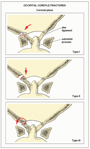
FIGURE 11.19 Anderson and Montesano classification of the occipital condyle fractures. (Modified from Anderson PA, Montesano PX. Morphology and treatment of occipital condyle fractures. Spine 1988;13:731-736.)

Type II injuries are associated with a vertical translation of the occiput on the cervical spine, secondary to the rupture of all occipitocervical ligaments. In type IIA, there is distraction between the occiput and C1, and vertical translation of the occiput on C1 is usually less than 2 mm. Vertical displacement greater than this represents failure of the tectorial membrane, alar ligaments, and occipitoatlantal facet joint capsules (Fig. 11.23B). If, conversely, the occipitoatlantal facet joint capsules remain intact and failure occurs at a more distal level of the tectorial membrane (i.e., at the level of the atlantoaxial facet joint ligaments), a type IIB injury results. In this type, there is also a vertical displacement of the spine, which occurs, however, between C1 and C2 rather than at the atlantooccipital level.

Type III injuries consist of posterior displacement of the occiput that is translated posteriorly to the atlas.

In all types of occipitocervical instability, associated injury to the transverse ligament and C1-2 instability should be suspected. Radiologic examination should include a standard lateral radiograph of the cervical spine that demonstrates the region from the occiput to the cervicothoracic junction. The articulations between occipital condyles and the atlanto-lateral masses must always be included and the clivus clearly visualized. In type III injuries, the clivus-odontoid line, which normally points into the tip of the odontoid process (see Fig. 11.3D), points posteriorly to the odontoid. Other suggestive findings on the lateral radiograph of the cervical spine are the absence of the projection of the mastoid processes over the odontoid and retropharyngeal soft-tissue swelling. CT is more effective for evaluating the occipitocervical junction. Using 1-mm thin contiguous sections with multiplanar reformation, the alignment of the occiput-C1 and C1-2 articulations can be readily discerned.


Fractures of the C1 and C2 Vertebrae


Jefferson Fracture

This fracture results from a blow to the vertex of the head. The axial forces transmitted symmetrically through the cranium and occipital condyles into the superior surfaces of the lateral masses of the atlas drive the lateral masses outward, resulting in bilateral, symmetrical fractures of the anterior and posterior arches of C1, which are invariably associated with disruption of the transverse ligaments (Fig. 11.24). Neck pain and unilateral occipital headache are characteristic clinical features of Jefferson fracture.

The best radiographic projections for demonstrating this injury is the open-mouth anteroposterior view and lateral projection (Fig. 11.25A,B).


CT may also be required in the evaluation of complex fractures (Fig. 11.25C,D). MRI only occasionally is performed (Fig. 11.26).


FIGURE 11.20 Fracture of the occipital condyle. A 23-year-old woman was injured in a motorcycle accident. (A) Coronal reformatted CT image shows a comminuted fracture of the right occipital condyle (arrows) and a fracture of the right lateral mass of the atlas (curved arrow). (B) 3D CT reconstructed image (bird’s eye view) shows no displacement of the fractured fragments (arrows) into the foramen magnum, classifying this injury as a type I.


FIGURE 11.21 Fracture of the occipital condyle. A 16-year-old girl was assaulted and sustained a blow injury to the head. Conventional radiographs of the skull and upper cervical spine were interpreted as normal. (A) Axial CT section through the base of the skull shows a type III fracture of the left occipital condyle (arrow). (B) Coronal reformatted CT image confirms the presence of an evulsion fracture (arrow).


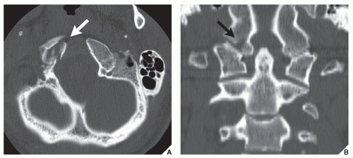
FIGURE 11.22 Fracture of the occipital condyle. An 18-year-old man was ejected from the convertible car during the accident. (A) Axial CT section through the base of the skull and (B) coronal reformatted CT image show a type III fracture of the right occipital condyle (arrows). Note displaced fragment of the occipital condyle toward the odontoid process.


FIGURE 11.23 Occipitocervical dislocation. (A) Lateral radiograph of the cervical spine in a 24-year-old man, who injured his head and neck in a motorcycle accident that resulted in complete quadriplegia, shows type I of occipitocervical dislocation: The occipital condyles are anteriorly displaced in relation to C1 vertebra. (B) In another patient, lateral radiograph demonstrates a type IIA vertical occipitocervical dislocation. (A, From Greenspan A, Montesano PX. Imaging of the spine in clinical practice. London, UK: Wolfe-Mosby-Gower Publishers; 1993, p. 2.19, Fig. 2.23; B, From Anderson PA, Montesano PX. Injuries to the occipitocervical articulation. In: Chapman MW, ed. Operative orthopaedics, vol. 4, 2nd ed. Philadelphia: JB Lippincott; 1993:2631-2640.)


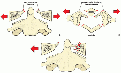
FIGURE 11.24 Jefferson fracture. The classic Jefferson fracture, seen here schematically on the anteroposterior (A) and axial (B) views, exhibits a characteristic symmetric overhang of the lateral masses of C1 over those of C2. Lateral displacement of the articular pillars results in disruption of the transverse ligaments. (C) On occasion, only unilateral lateral displacement of an articular pillar may be present.


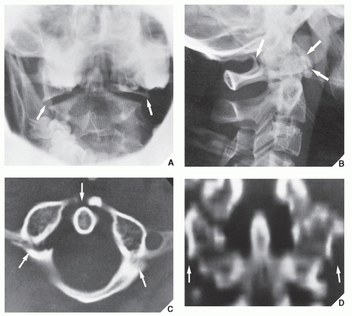
FIGURE 11.25 Jefferson fracture. A 19-year-old man sustained a neck injury while being mugged. (A) Open-mouth anteroposterior radiograph of the cervical spine shows lateral displacement of the lateral masses of the atlas (arrows), suggesting a ring fracture of C1. (B) Lateral radiograph demonstrates fracture lines of the posterior and anterior arch of C1 (arrows). (C) CT section demonstrates two fracture lines of the posterior arch and a fracture of the anterior arch (arrows). (D) CT coronal reformation confirms lateral displacement of the lateral masses (arrows).


FIGURE 11.26 Jefferson fracture. A 56-year-old man was hit on the top of the head during the industrial accident. (A) Later radiograph of the cervical spine shows a fracture of C1 (arrow). (B) Axial CT section and (C) 3D CT reconstructed image confirm unilateral fracture of the left anterior and posterior arches of C1 (arrow).


Fractures of the Odontoid Process

Fractures of the dens belong to the group of flexion injuries, although at times forces causing hyperextension of the cervical spine may also result in damage to the odontoid process. In hyperflexion injuries, the odontoid process is usually displaced anteriorly, and there may be associated forward subluxation of C1 or C2. Hyperextension injuries, however, usually cause the odontoid to be displaced posteriorly, with posterior subluxation of C1 or C2.

Several classifications of odontoid fractures have been proposed, based on the site and amount of displacement of a fracture. The system suggested by Anderson and D’Alonzo, however, is practical and has gained wide acceptance because of its emphasis on the most important feature of such fractures—their stability (Fig. 11.27):


Type I: Fractures of the body of the dens distal (cephalad) to the base. They are usually obliquely oriented and are considered stable injuries. Conservative treatment usually suffices for healing. Some authorities do not recognize type I fractures, postulating that these “injuries” in fact represent a nonunited secondary ossification center (ossiculum terminale of Bergman) or os odontoideum.

Type II: Transverse fractures through the base of the odontoid are unstable injuries (Fig. 11.28). Conservative treatment has been complicated by nonunion in approximately 35% of cases; therefore, surgical fusion is the usual method of treatment.

Type III: Fractures through the base of the odontoid extending into the body of the axis are stable injuries (Figs. 11.29 and 11.30). Conservative treatment is usually sufficient.

The best techniques for demonstrating fractures of the dens are the anteroposterior view, including the open-mouth variant, or Fuchs projection, and the lateral projection; thin-section trispiral tomography (at present rarely used) may also prove effective in delineating ambiguous or subtle features (see Figs. 11.28C,D and 11.29C).

CT detection of the dens fractures, particularly type II, may be difficult if the axial sections are obtained parallel to the usually horizontally oriented fracture line. For this reason, it is essential to obtain routinely reformatted images in coronal and sagittal planes (Fig. 11.30).


Hangman’s Fracture

In 1912, Wood-Jones described the pathomechanism associated with execution by hanging. He found that hyperextension and distraction resulted in bilateral fractures through the pedicles of the axis, with anterior dislocation of the body and subsequent tearing of the spinal cord. A similar fracture,


which in fact constitutes traumatic spondylolisthesis of C2, is common in automobile accidents, when the face strikes the windshield before the vertex of the head, forcing the neck into hyperextension. This injury, which accounts for 4% to 7% of all cervical spine fractures and dislocations, may present as simple, nondisplaced fractures through the pedicles of the axis or as fractures through the arches with anterior subluxation and angulation of C2 onto C3 (Fig. 11.31). The fracture line usually lies anterior to the inferior articular facet of C2 in both variants, but displaced fractures are more often associated with ligament disruption and intervertebral disk injuries. The best projection for demonstrating this injury is the lateral radiograph (Fig. 11.32).


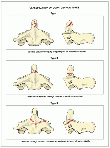
FIGURE 11.27 Classification of odontoid fractures. (Modified from Anderson LD, D’Alonzo RT. Fractures of the odontoid process of the axis. J Bone Joint Surg [Am] 1974;56A:1663-1674.)


FIGURE 11.28 Fracture of the odontoid process. A 62-year-old man sustained a flexion injury of the cervical spine in an automobile accident. Open-mouth anteroposterior (A) and lateral (B) radiographs demonstrate a fracture line at the base of the odontoid process, but the details of this injury cannot be well appreciated. Thin-section trispiral tomographic sections in the anteroposterior (C) and lateral (D) projections confirm the fracture at the base of the dens. This is a type II (unstable) fracture.


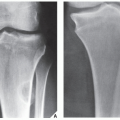
FIGURE 11.29 Fracture of the odontoid process. A 24-year-old man fell on his head in a skiing accident. Open-mouth anteroposterior (A) and lateral (B) radiographs of the cervical spine demonstrate a fracture of the odontoid process extending into the body of C2 (arrows)—a type III stable fracture. The diagnosis was confirmed by trispiral tomography in the anteroposterior projection (C).


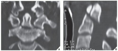
FIGURE 11.30 CT demonstration of fracture of the odontoid process. A 50-year-old man sustained a flexion neck injury during a motorcycle accident. The conventional radiographs of the cervical spine suggested odontoid fracture but were not conclusive. Coronal (A) and sagittal (B) reformatted CT images clearly demonstrate a type II odontoid fracture.


FIGURE 11.31 Hangman’s fracture. This injury may present as nondisplaced fractures through the arches of C2, as seen here schematically on the lateral (A) and axial (B) views, or as displaced fractures with anterior angulation (C) and (D) associated with disruption of ligaments, the intervertebral disk, or articular facets.

Hangman’s fractures (which probably should be correctly called hanged man fractures) have been classified into three types (Fig. 11.33). Type I injury is characterized by the fracture through the pedicle of C2 extending between the superior and inferior facets. Type II injury constitutes a type I fracture with concomitant disruption of intervertebral disk C2-3. Type III injury consists of a type II fracture associated with a C2-3 facet dislocation.

Only gold members can continue reading. Log In or Register to continue

Stay updated, free articles. Join our Telegram channel

Jul 24, 2016 | Posted by in MUSCULOSKELETAL IMAGING | Comments Off on Spine

Full access? Get Clinical Tree

Get Clinical Tree app for offline access