Steady State Free Precession
Mark Doyle
OVERVIEW
Steady state free precession (SSFP) imaging is the means of combining all three echo types: gradient, spin, and stimulated; to form a very efficient, signal rich image. Here we will quickly review the basic properties of k-space and the role of gradients, and develop the mechanism utilized in SSFP imaging. The major application area discussed here for SSFP is cardiac functional imaging.
K-SPACE
The magnetic resonance imaging (MRI) data space is termed k-space. Briefly, each image requires a two-dimensional (2D) arrangement of signal data, termed k-space. To form an image, the k-space data undergoes Fourier transformation. Here we represent k-space as a series of parallel lines, each line corresponding to an individual acquisition of an MRI echo signal. Most conventional MR imaging sequences fill k-space one line at a time. To encode each k-space line requires application of two separate gradients:
Frequency encoding, for example, X
Phase encoding, for example, Y
Magnetic gradients are applied to accomplish frequency encoding and phase encoding.
SIGNAL PREPARATION AND ENCODING
A basic property of nuclear spins is that an individual nuclear species precess at a field-dependent frequency, ω, given by the Larmor equation:
A magnetic gradient applied to the body causes nuclear spins in different locations to precess at field-dependent frequencies:
Low field strength, low precession rate
High field strength, high precession rate
The phase encoding gradient is applied before signal detection, and therefore the signal is required to be delayed from the slice selection time point to the time when it is measured. Although this time is only a matter of milliseconds, it is nevertheless required, and requires special treatment. The signal echo is the means of delaying the signal to allow spin preparation to take place before sampling of k-space. Here we discuss the stimulated echo, which is one component contributing to SSFP.
STIMULATED ECHO
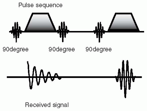
In a stimulated echo, the initial radiofrequency (RF) pulse is followed by a positive gradient; after some time a second RF pulse is applied with no gradient; after a second delay, a third RF pulse is applied, which is followed by a positive gradient. Under these conditions, spins
refocus as an echo following the third RF pulse (see Fig. 27-1). Therefore, in a stimulated echo the essential features are as follows:
refocus as an echo following the third RF pulse (see Fig. 27-1). Therefore, in a stimulated echo the essential features are as follows:
Apply an initial 90-degree RF pulse
Time delay
Apply the second 90-degree RF pulse
Time delay
Apply the third 90-degree RF pulse
Imaging gradients are balanced after the first and third RF pulses
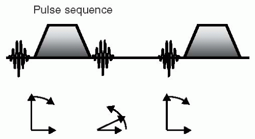 FIGURE 27-2 The first radiofrequency (RF) pulse (horizontal arrow) brings the magnetization vector, M0 (vertical arrow), into the transverse plane, and a free induction decay (FID) signal is seen. The spins are dephased by the imaging gradient. The second RF pulse (horizontal arrow) puts the spins back up along the Z-axis, and therefore no signal is generated. The third RF pulse (horizontal arrow) brings the spins (vertical arrow) back to the transverse plane, where the second gradient refocuses the spins, and an echo signal is seen. |
One way of thinking about the stimulated echo is to consider the combination of the second and third 90-degree RF pulses to be equivalent to a single 180-degree refocusing RF pulse, as used in spin echo imaging (see Fig. 27-2). The significance of splitting the pulse into two components with a time delay between them will become apparent in the following discourse.
STIMULATED ECHO EFFICIENCY
Following the initial 90-degree RF pulse, all spins are brought down into the transverse plane. During the delay following this pulse, spins dephase because of the application of a magnetic gradient. However, at the time of application of the second RF pulse, only 50% of spins are effectively put back along this axis. To appreciate this, consider the spin system resolved into X and Y components in the transverse plane (see Fig. 27-3):
The applied gradient dephases spins until no net signal is seen. At this point, resolving spins along the X- and Y-axes, we see that there are equal spin components along the positive and negative X- and Y-axes.
The second RF pulse only acts on the spin component that is perpendicular to the RF magnetization, and therefore if the RF is applied along the Y-axis, only the component of M0 along the X-axis will be affected by the RF pulse. In this case, this corresponds to 50% of the signal.
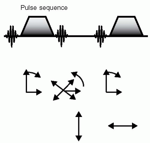 FIGURE 27-3 The efficiency of the stimulated echo is limited by the percentage of spins returned to the Z-axis by the second radiofrequency (RF) pulse. The first RF pulse acts on 100% of the signal along the Z-axis (vertical arrow). Owing to the dephasing action of the first gradient, at the time of the second RF pulse, the spins are completely dephased. At this stage, they can be resolved into X and Y components (crossed arrows). The second RF pulse (horizontal arrow
Get Clinical Tree app for offline access
Stay updated, free articles. Join our Telegram channel
Full access? Get Clinical Tree


|
