Temporomandibular Joint
Thomas H. Berquist
Anatomy
Key Facts
The temporomandibular joint (TMJ) is a synovial joint divided by a disc into superior and inferior compartments.
The normal disc is biconcave.
The posterior band is thicker and separated from the anterior band by the thin intermediate zone, giving the disc a “bow-tie” configuration.
The posterior attachment (bilaminar zone) contains the neurovascular supply for the disc.
When the mouth is closed, the disc is at the apex of the mandibular condyle.
The normal disc remains centered over the condyle as the mouth opens.
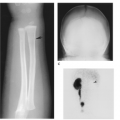
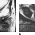
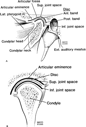 FIGURE 2-1 Normal TMJ in the sagittal (A) and coronal (B) planes. |
Protocols
Imaging of the TMJ can be accomplished with multiple methods. Routine radiographs, computed tomography, and magnetic resonance imaging (MRI) are used most commonly in our practice.
Routine radiographs:
Anteroposterior
Towne
Oblique views of each TMJ
Computed tomography:
120 kVp, 270 mA, 25-cm field of view (FOV)
1- to 2-mm axial sections with bone and soft tissue windows
Reformatted sagittal and coronal images with 1.0-mm sections
MRI—basic approach:
3-inch dual-coupled coils
FOV: 10 to 12 cm 256 × 256 matrix, one excitation
Axial scout images (20/5, 40 degrees FA, 256 × 128 matrix, 4- to 5-mm–thick sections) through the TMJ
Technique 1:
Sagittal or oblique sagittal images in the closed and open positions, 256 × 256 matrix, and three acquisitions. T1-weighted (spin-echo 416/17) images (3 mm thick). Fast spin-echo (turbo spin-echo 300/19) images (3 mm thick).
Coronal fast spin-echo (turbo spin-echo 1500/19) images optional if disc poorly visualized on sagittal images or medial or lateral displacement is suspected.
Technique 2—motion studies:
Sagittal gradient-echo images (4-mm–thick sections, 80/11, 30 degrees FA, 256 × 256 matrix, one acquisition, FOV 10–12 cm). Each image obtained as mouth is opened with incremental device (3 mm per image). Images obtained from closed to open. Cine-loop motion created.
Optional coronal T1- or T2-weighted images.
Suggested Reading
Berquist TH, Helms CA. The temporomandibular joint. In: Berquist TH, ed. MRI of the musculoskeletal system, 5th ed. Philadelphia: Lippincott Williams & Wilkins; 2006:98–120.
Gibbs SJ, Simmons C. A protocol for magnetic resonance imaging of the temporomandibular joints. Cranio 1998;16:236–241.
Internal Derangement
Key Facts
The disc is normally at the 12 o’clock position with the mouth in the closed position. There is some degree of displacement in up to 34% of asymptomatic patients.
Internal derangement is defined as an abnormal relationship or position of the disc to the condyle and articular eminence.
The cause is unknown, but trauma, malocclusion, bruxism, hypermotility, ligament laxity, condylar abnormalities, and stress are implicated.
Females outnumber males 5:1.
Internal derangement is a progressive process.
Initially anterior, medial, or lateral displacement occurs when the mouth is closed, which reduces with opening.
The disc no longer reduces as elasticity decreases.
The disc becomes deformed with secondary bony changes.
Anterior displacement is most common, and 80% to 90% are bilateral. Stuck disc occurs in 4% to 11%, medial or lateral displacement occurs in 5%, and posterior displacement occurs in 1%.
Clinical symptoms include pain, clicking, and reduced motion.
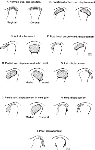 FIGURE 2-2 Disc displacement categories: normal (A), anterior displacement (B), partial anterior displacement in lateral joint (C), partial anterior displacement in medial joint (D), rotational anterolateral displacement (E), rotational anteromedial displacement (F), lateral displacement (G), medial displacement (H), posterior displacement (I). |
Suggested Reading
Aoyama S, Kino K, Amagasa T, et al. Clinical and magnetic resonance imaging study of unilateral sideways disc displacement of the temporomandibular joint. J Med Dent Sci 2002;49:89–94.
Related posts:

Stay updated, free articles. Join our Telegram channel

Full access? Get Clinical Tree


