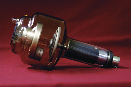
• Describe the construction and purpose of the x-ray tube housing. • Identify the principal parts of the x-ray tube and their purposes. • Describe the operation of the principal parts of the x-ray tube. • Discuss anode designs and construction. • Explain the line-focus principle. • Explain the anode heel effect. • Discuss cathode designs and construction. • Trace the path of electricity through the x-ray circuit and x-ray tube connecting the selections on the operating console to the functions within the unit. • Use tube rating charts, anode cooling charts, and housing cooling charts. • Employ methods of safe x-ray tube operation and extending x-ray tube life. Chapter 1 provided a general discussion of the x-ray tube head assembly and the function of the major parts of the design. Chapter 4 discussed the components of the x-ray circuit and the events that lead to the production of x-rays in the x-ray tube. This chapter examines the x-ray tube itself (Figure 5-1), its general construction, and how it works. The sole purpose for manipulating electricity in an x-ray circuit is to create the environment in the x-ray tube necessary for x-ray production. The need for the radiographer to understand the x-ray tube is twofold. First, as was described in Chapter 4, the radiographer must have a basic understanding of how the tube works to competently and safely formulate exposure techniques and minimize patient radiation dose. Second, such an understanding is critical to extending the life of the tube and to avoid damaging it. The general construction of the tube head assembly is discussed first. Recall that the x-ray tube is situated in a protective housing that provides solid, stable mechanical support. This housing is a lead-lined metal structure that also serves as an electrical insulator and thermal cushion for the tube itself (Figure 5-2). X-ray production is a rather inefficient process and much of the electrical energy that goes into it is converted to heat. The design of the housing incorporates an oil bath and cooling fans to help dissipate heat away from the tube, protecting it from thermal damage. The tube is immersed in the oil bath, which draws heat away from the tube. The cooling fans circulate air around the assembly, which also helps dissipate heat. Because of the large current and voltage needed to produce x-rays, electrical insulation is necessary. Two large electrical cables enter the housing and are securely attached to the x-ray tube through special high-voltage receptacles. Finally, although x-rays are perceived as being produced and traveling in one direction out through the collimator to the patient and image receptor, this is not the case. X-rays are produced isotropically (in all directions) and another role of the housing is to absorb most of the photons traveling in directions other than toward the patient. This is called leakage radiation and the housing design reduces this radiation to less than 100 mR/hr, as required by regulation. Although there are several specialty designs of the x-ray tube, they do have basic components in common. This text focuses on the design used for general medical radiography. The general-purpose x-ray tube is an electronic vacuum tube that consists of an anode, a cathode, and an induction motor all encased in a glass or metal enclosure (envelope). Figure 5-3 provides a labeled illustration of this design. Recall that the anode is the positive end of the tube and the cathode is the negative end of the tube. The anode incorporates an anode target and an induction motor, half of which is inside and half of which is outside the protective enclosure; the anode is discussed in detail shortly. The cathode consists of the focusing cup and filament with its supporting wires. The anode is the positive end of the tube. It provides the target for electron interaction to produce x-rays and is an electrical and thermal conductor. Remember that electricity is flowing through the x-ray tube and the electrons flowing from cathode to anode are a part of that flow of electricity. Some of the electrons interact with the target to produce x-rays (see Chapter 6), and the rest continue as current flow through the x-ray circuit. Remember, too, that a tremendous amount of heat is also generated during the process and the anode is designed to dissipate this heat. There are two designs for the anode. One is the stationary anode (Figure 5-4, A). This is basically a tungsten button embedded in a copper rod. It is called stationary because the target does not move. Stationary anodes were used in old tube designs and may still be found in dental x-ray units or those requiring very small exposure techniques. The primary disadvantage of this design is that, because the electrons always hit the same small target area, heat builds up rapidly and can damage the tube. This problem limits the exposure technique factors that can be used and this limitation spurred the development of rotating-anode designs. The rotating-anode design is used in general-purpose tubes today (Figure 5-4, B
The X-ray Tube
Introduction
General Tube Construction
Housing
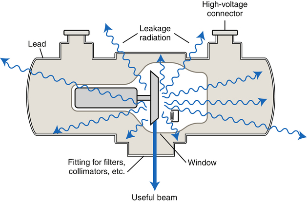
Protective housing with the x-ray tube situated inside. The design of the housing serves as an electrical insulator and thermal cushion for the x-ray tube in addition to being a protective device against physical damage.
X-ray Tube
Anode
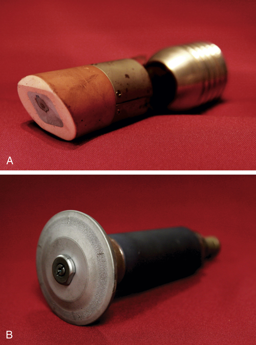
A is a stationary anode removed from the glass envelope. Note the silver-colored tungsten button and the discolored area where electrons interacted with it. B is a rotating anode removed from the glass envelope. The focal track along the edge of the disc and some damage from extensive use is visible.
![]()
Stay updated, free articles. Join our Telegram channel

Full access? Get Clinical Tree


The X-ray Tube
 Critical Concept 5-1
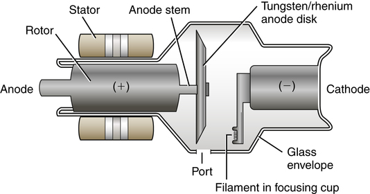
 Critical Concept 5-2