Transesophageal Echocardiography of the Thoracic Aorta
ALTHOUGH SIMPLE IN STRUCTURE, THE thoracic aorta is a crucial component of the routine perioperative transesophageal echocardiography (TEE) examination. Pathologies such as atheroma, aneurysms, and dissections can be readily diagnosed and inspected in the operating room. Likewise, TEE can help guide the insertion of cannulas, stents, and intra-aortic balloon pumps during the actual surgical procedure. It is therefore imperative that the intraoperative echocardiographer have a firm grasp on both the anatomy and potential abnormalities of this vital blood vessel.
ANATOMY AND TEE IMAGING
The basic structure of the aorta is similar to that of an upside-down letter “J,” albeit with a slight twist (see Fig. 17.1). The aortic valve annulus, leaflets, and sinuses of Valsalva comprise the beginning of the thoracic aorta, collectively known as the aortic root. The ascending aorta, which is the start of the tubular portion, begins at the sinotubular junction (STJ), travels cephalad, and extends to the origin of the innominate (a.k.a. brachiocephalic) artery. The aortic arch begins at this point and travels horizontally to the origin on the left subclavian artery. The descending aorta begins just distal to the left subclavian artery, at a region known as the aortic isthmus, and travels caudad going through the diaphragm.
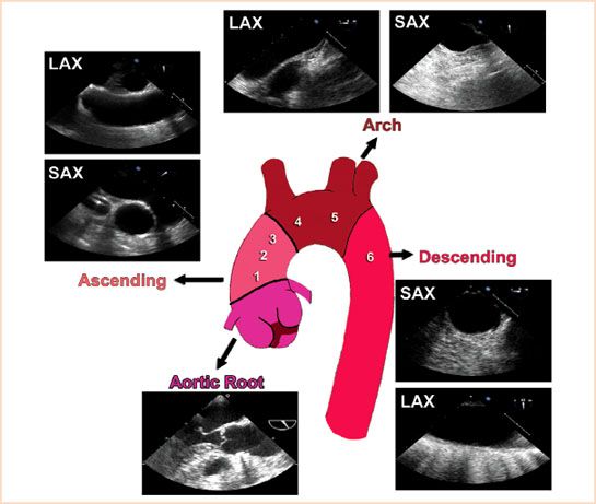
FIGURE 17.1 Basic anatomy of the aorta and TEE views. The thoracic aorta resembles a slightly twisted “J” and is commonly divided into six zones (shown as 1 to 6 in figure).
It is important to keep this overall shape of the aorta in mind during its examination. The vertical nature of the descending portion explains why a short-axis (SAX) view of this section is typically obtained at an omniplane angle of around 0 degrees, while the SAX view of the arch, which is horizontal in nature, is at 90 degrees. The reverse is true for the long-axis (LAX) views, with the descending and arch portions of the aorta obtained at 90 degrees and 0 degrees, respectively (1). It is also important to keep in mind that the relationship between the esophagus and the aorta switches as they travel from the abdomen into the thoracic cavity (see Fig. 17.2). At the level of the diaphragm, the aorta is posterior to the esophagus, while at the level of the arch, the aorta is anterior to it. Because of this changing orientation, it is very difficult for the echocardiographer to designate anterior/posterior and left/right while examining the descending aorta.
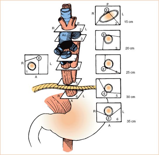
FIGURE 17.2 Relationship between the esophagus and aorta at different levels of the thoracic esophagus. (From Estafanous FG, Barash PG, Reves JG, eds. Cardiac anesthesia principles and clinical practice, 2nd ed. Philadelphia: Lippincott Williams & Wilkins, 2001:785, with permission).
For purposes of surgery and echocardiography, the thoracic aorta can be divided into six zones (2). The first three zones are within the ascending aorta, with zone 1 closest to the aortic root, zone 2 the typical site for proximal anastomosis of coronary grafts, and zone 3 where aortic cross-clamping for cardiopulmonary bypass (CPB) occurs. The aortic arch is divided into two halves, creating zones 4 and 5. The aortic cannula is often placed within the distal region of zone 3 to proximal region of zone 4. The descending aorta comprises zone 6. Because of the interposition of the trachea and left mainstem bronchus, TEE cannot reliably image zones 3 and 4, which is the rationale for performing epiaortic scanning (3) (Fig.17.1).
Because of the sheer length of the structure, the thoracic aorta can be viewed in many of the standard imaging planes. However, a systematic approach to its examination is recommended to ensure all possible sections are visualized. One common method is to begin its examination after obtaining the transgastric views of the left ventricle and turning the probe to the left until the descending aorta is seen in SAX at 0 degrees. From here, the depth is typically set to 6 to 8 cm and the probe is withdrawn, following the aorta until the circular view of the descending in SAX becomes the tubular view of the arch in LAX (Video 17.1). The omniplane angle can then be adjusted to about 90 degrees to obtain the SAX of the arch and the probe advanced, following the descending aorta down to the diaphragm in LAX (Video 17.2). The process can be repeated using color flow Doppler to help visualize dissections or coarctations of the descending aorta.
The ascending aorta can be visualized by first obtaining a midesophageal LAX of the aortic valve at a typical omniplane angle of 110 to 140 degrees, and slowly withdrawing the probe to obtain imaging of the ascending aorta. By using the right pulmonary artery as an imaging window it is usually possible to see up
to zone 2. The omniplane angle can then be decreased by 90 degrees to obtain a SAX of the ascending aorta and the probe advanced to follow the aortic root down to the aortic valve in SAX (Video 17.3). The views used to scan the thoracic aorta are provided in Figure 17.1, and while their order of acquisition is not important, all are required for a complete examination.
Acute Aortic Syndromes
Acute aortic syndromes are a collection of life-threatening conditions including aortic dissection, intramural hematoma (IMH), and penetrating aortic ulcers. Acute dissection of the ascending aorta, perhaps the best studied of these entities, has a widely quoted mortality rate of 1% to 2% per hour upon presentation (4). Timely diagnosis is obviously critical so that appropriate surgical intervention can be instituted.
Acute Aortic Dissection
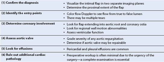
An aortic dissection begins with a tear in the intimal layer of the aorta. The tear allows blood to enter and separate the intima from the media or adventitia, creating a “flap” of tissue separating the true aortic lumen from the false lumen (Fig. 17.3, Video 17.4). It is the visualization of this flap that makes the diagnosis. While in the past, aortography was considered the “gold standard” for diagnosis of aortic dissection, it is very rarely used as a first-line test today due to its invasiveness and lower sensitivity than other modalities. A recent survey of the International Registry of Acute Aortic Dissection (IRAD) database showed that contrast-enhanced computed tomography (CT) was the first diagnostic test in 68% of cases since the year 2000, with TEE used for initial diagnosis in almost all of the remainder (28%). Even if surgical intervention is initiated based upon CT findings, intraoperative TEE still plays an essential role in confirming the diagnosis and helping to guide surgical repair. Important aspects for the intraoperative echocardiographer to address during the examination are summarized in Table 17.1(5).
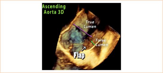
FIGURE 17.3 Aortic dissection flap. Once a tear in the intimal layer of the aorta occurs, blood enters and separates the intima from the medial or adventitial layers. This creates two lumens, the native or “true” lumen (denoted by purple arrow), and the space due to the separation known as the “false” lumen (denoted by green arrow).
TABLE 17.1 Role of Intraoperative TEE in Acute Ascending Aortic Dissection
Thoracic aortic dissections are commonly classified by either the Stanford (Type A or B) or DeBakey (Type I, II, or III) system (Fig. 17.4). Acute dissections of the ascending aorta (i.e., Stanford A, or DeBakey Types I and II) are considered surgical emergencies since medical management has a 14-day mortality of about 50% (6). Dissections of the descending aorta (i.e., Stanford B, or DeBakey Type III) are less lethal and not generally taken to the operating room emergently unless there are ischemic complications such as renal or visceral malperfusion.
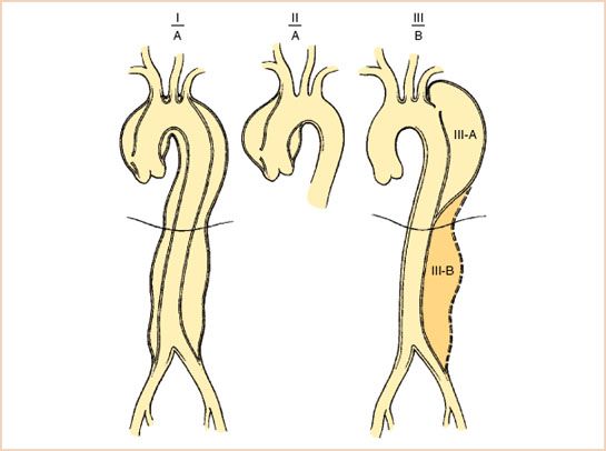
FIGURE 17.4 The Stanford (A and B) and DeBakey (I, II, III) classification systems for thoracic aorta dissections. (From Crawford ES, Crawford JL. Diseases of the aorta. Baltimore: Williams & Wilkins, 1984:174, with permission.)
As stated earlier, the hallmark finding of an acute aortic dissection on TEE is the visualization of the intimal flap. The proximal extent of the flap is important to determine, since this typically governs the need for acute surgical treatment. In an ascending aorta dissection, most patients do not undergo angiography due to the acuity of the situation, so it is also useful to determine if the proximal extension involves any coronary arteries. The dissection flap is usually very irregularly shaped and highly mobile (Video 17.5). Visualizing the flap in two separate imaging planes (Fig. 17.5) is important in order to distinguish artifacts from true dissection flaps. One such confounder is the presence of a pulmonary artery catheter, which can create reverberation artifacts mimicking a flap (Fig. 17.6). When in doubt, this can be remedied by pulling the catheter back and seeing if the flap remains. Other sources of linear artifacts include calcifications on the aortic valve or root and atherosclerosis of the ascending aorta (7). They can typically be distinguished from a true dissection by their lack of rapid, oscillatory movement, their tendency to cross known anatomic boundaries, and their indistinct structural borders.
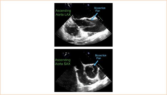
FIGURE 17.5 Ascending aorta dissection flap in short and long axis. A dissection flap is irregularly shaped and typically mobile. It should be visualized in two separate views to minimize the chance of mistaking an artifact for a flap.
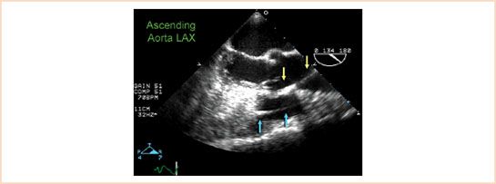
FIGURE 17.6 Pulmonary artery catheter mimicking aortic dissection flap. The false appearance of a dissection flap in the ascending aorta is often due to the presence of a pulmonary artery catheter in the right ventricle (delineated by blue arrows) causing a reverberation artifact (delineated by yellow arrows).
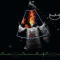
Once the dissection flap is visualized, it is useful to determine where the break in the intima (a.k.a. the “tear” or “entry point”) has occurred, since one of the primary aims of surgical treatment is to excise this region. Color flow Doppler is often used to visualize a turbulent jet flowing from the true lumen into the false lumen (Fig. 17.7, Video 17.6). The true lumen can usually be differentiated from the false lumen due to its expansion during systole (Video 17.7). In addition, the false lumen is often larger, and frequently has spontaneous echo contrast or thrombus within it, particularly in the descending aorta (8).
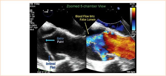
FIGURE 17.7 Identification of the entry point. The break in the intimal layer is known as the entry point or tear. Use of color flow Doppler, as seen in this color compare image, can help visualize blood flow entering the false lumen at the site of the tear.
Intramural Hematoma
While the initiating event for the classical aortic dissection is a break in the intimal layer, the underlying cause of an IMH is thought to be a rupture of vasa vasorum in the medial layer (9). This blood accumulation causes a thickening of the medial layer which may progress to intimal fracture, and subsequent flap formation like a classic aortic dissection, or frank aortic rupture. The mortality from IMH is dependent on the location (i.e., ascending or descending aorta) and is similar to that of classic aortic dissection (10). As such, the Stanford classification system is applied, with Type A considered a surgical emergency.
Unlike the classic aortic dissection, there is no intimal flap. On TEE imaging, IMH appears as a thickening of the medial layer of the aorta (Fig. 17.8). This typically measures 7 ± 2 mm in Type A cases, and
15 ± 6 mm in Type B (11). Other features may include echolucency within the medial layer, and medial displacement of calcium in the intimal layer. It is important to note that atherosclerotic plaques appear above the intimal layer, while IMHs occur below the intimal layer.
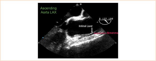
FIGURE 17.8 Intramural hematoma of the ascending aorta. Thickening of the media beneath the intimal layer is demonstrated in this Type A intramural hematoma. Video 17.8.
Related posts:
Stay updated, free articles. Join our Telegram channel

Full access? Get Clinical Tree


