view obtained with a 15-degree cephalad tilt of the radiographic tube (Fig. 5.13). Stress views in this projection, for which weights are strapped to the patient’s forearms, are often mandatory, especially in suspected occult acromioclavicular subluxation (see Fig. 5.88). Fracture of the scapula may require a transscapular (or Y) view for sufficient evaluation (Fig. 5.14). Fracture of the acromion can be adequately evaluated on the shoulder outlet view. This projection is obtained similarly to the Y view of the shoulder girdle; however, the central beam is directed toward the superior aspect of the humeral head and is angled approximately 10 to 15 degrees caudad (Fig. 5.15). This view is also effective in demonstration of morphologic types of the acromion (Fig. 5.16; see also Fig. 5.28).
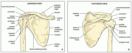 FIGURE 5.1 Osseous structures of the shoulder. Anterior (A) and posterior (B) views of the osseous components of the shoulder girdle. |
is externally rotated (or the patient is positioned prone) to force the air to move posteriorly.
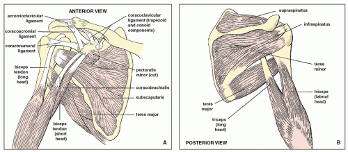 FIGURE 5.2 Muscles, ligaments, and tendons of the shoulder. Anterior (A) and posterior (B) views of the muscles, ligaments, and tendons of the shoulder girdle. (Modified from Middleton WD, Lawson TL. Anatomy and MRI of the joints. New York: Raven Press; 1989.) |
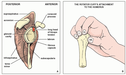 FIGURE 5.3 Rotator cuff. (A) Schematic of the glenoid fossa (with the humerus removed) shows the location of the muscles of the rotator cuff and the intracapsular portion of the long head of the biceps tendon. (B) Four muscles form the “rotator cuff”: subscapularis (SS), supraspinatus (S), infraspinatus (I), and teres minor (T). They envelop the joint, blend with the capsule, and grasp their four points of attachment to the humerus, as does the hand in the figure, thus maintaining the integrity of the joint. (Modified from Anderson JE. Grant’s atlas of anatomy, 8th ed. Baltimore: Williams & Wilkins; 1983.) |
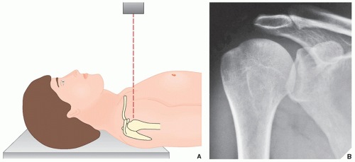 FIGURE 5.4 Anteroposterior view. (A) For the standard anteroposterior projection of the shoulder, the patient may be either supine, as shown here, or erect; the arm of the affected side is fully extended in the neutral position. The central beam is directed toward the humeral head. (B) On the radiograph obtained in this projection, the humeral head is seen overlapping the glenoid fossa. The glenohumeral joint is not well demonstrated. |
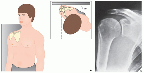 FIGURE 5.5 Grashey view. (A) For the anteroposterior view of the shoulder that demonstrates the glenoid in profile (Grashey projection), the patient may be either erect, as shown here, or supine. He or she is rotated approximately 40 degrees toward the side of the suspected injury, and the central beam is directed toward the glenohumeral joint. (B) The radiograph in this projection (posterior oblique view) shows the glenoid in true profile. Note that the glenohumeral joint space is now clearly visible. |
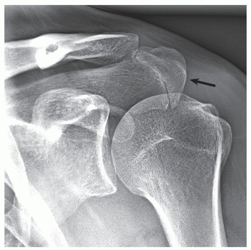 FIGURE 5.6 Grashey view of os acromiale. A 45-year-old man presented with clinical history of shoulder impingement. A Grashey projection shows an os acromiale (arrow). This normal developmental variant should not be mistaken for a fracture. |
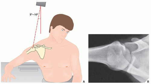 FIGURE 5.7 Axillary view. (A) For the axillary view of the shoulder, the patient is seated at the side of the radiographic table, with the arm abducted so that the axilla is positioned over the film cassette. The radiographic tube is angled approximately 5 to 10 degrees toward the elbow, and the central beam is directed through the shoulder joint. (B) The radiograph in this projection demonstrates the exact relationship of the humeral head and the glenoid. |
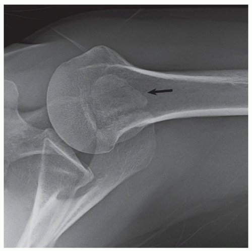 FIGURE 5.8 Axillary view of os acromiale. A 48-year-old woman presented with history of shoulder pain. An arrow points to os acromiale. |
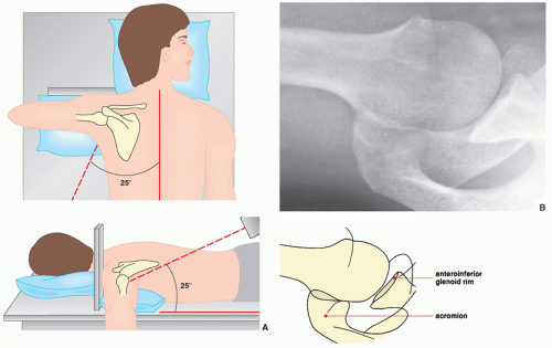 FIGURE 5.9 West Point view. (A) For the West Point view of the shoulder, the patient lies prone on the radiographic table, with a pillow placed under the affected shoulder to raise it approximately 8 cm. The film cassette is positioned against the superior aspect of the shoulder. The radiographic tube is angled toward the axilla at 25 degrees to the patient’s midline and 25 degrees to the table’s surface. (B) On the radiograph in this projection, the relationship of the humeral head and the glenoid can be as sufficiently evaluated as on the axillary view, but the anteroinferior glenoid rim, which is seen tangentially, is better visualized. |
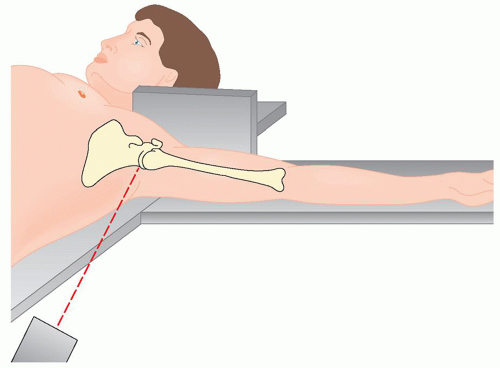 FIGURE 5.10 Lawrence view. For the Lawrence variant of the axillary view of the shoulder, the patient lies supine on the radiographic table, with the affected arm abducted up to 90 degrees. The film cassette is positioned against the superior aspect of the shoulder with the medial end against the neck, which places the midportion of the cassette level with the surgical neck of the humerus. The radiographic tube is at the level of the ipsilateral hip and is angled medially toward the axilla. The amount of angulation depends on the degree of abduction of the arm: Less abduction requires increased medial angulation. The central beam is directed horizontally slightly superior to the midportion of the axilla. The Lawrence view demonstrates the same structures as the standard axillary view. |
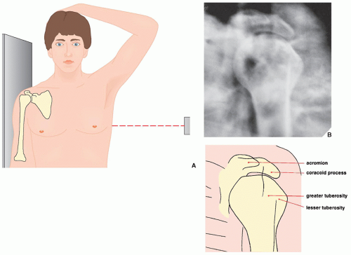 FIGURE 5.11 Transthoracic lateral view. (A) For the transthoracic lateral projection of the proximal humerus, the patient is erect with the injured arm against the radiographic table. The opposite arm is abducted so that the forearm rests on the head. The central beam is directed below the axilla, slightly above the level of the nipple. (B) The radiograph obtained in this projection demonstrates the true lateral view of the proximal humerus. |
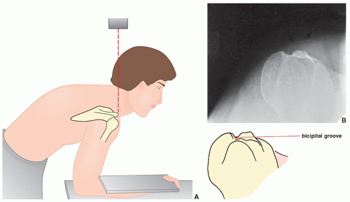 FIGURE 5.12 Bicipital groove view. (A) For a tangent film in the superoinferior projection visualizing the bicipital groove (sulcus), the patient is standing and leaning forward, with the forearm resting on the table and the hand in supination. The film cassette rests on the patient’s forearm. The central beam is directed vertically toward the bicipital groove, which has been marked on the skin. (B) On the radiograph obtained in this projection, the bicipital groove is clearly demonstrated. |
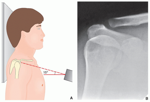 FIGURE 5.13 Acromioclavicular view. (A) To evaluate the acromioclavicular articulation, the patient is erect, with the arm of the affected side in the neutral position. The central beam is directed 15 degrees cephalad toward the clavicle. As overexposure of the film will make it difficult to evaluate the acromioclavicular joint properly, the radiographic factors should be reduced to approximately 33% to 50% of those used in obtaining the standard anteroposterior view of the shoulder. (B) The radiograph obtained in this projection shows the normal appearance of the acromioclavicular joint. |
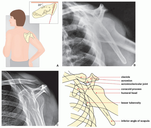 FIGURE 5.14 Transscapular view. (A) For the transscapular (or Y) projection of the shoulder girdle, the patient is erect, with the injured side against the radiographic table. The patient’s trunk is rotated approximately 20 degrees from the table to allow for separation of the two shoulders (inset). The arm on the injured side is slightly abducted and the elbow flexed, with the hand resting on the ipsilateral hip. The central beam is directed toward the medial border of the protruding scapula. (This view may also be obtained with the patient lying prone on the radiographic table and the uninjured arm elevated approximately 45 degrees.) (B) The radiograph obtained in this projection provides a true lateral view of the scapula, as well as an oblique view of the proximal humerus. (C) Same structures can be visualized on the radiograph obtained without abduction of the arm. |
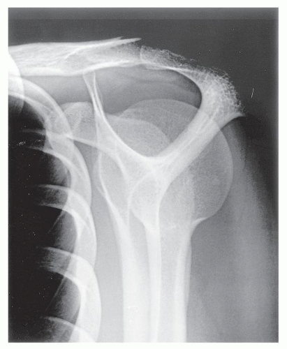 FIGURE 5.15 Outlet view. This projection shows the same anatomic structures as demonstrated on the Y view of the shoulder girdle. In addition, coracoacromial arch and space occupied by the rotator cuff are well imaged. |
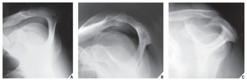 FIGURE 5.16 Types of the acromion. On the outlet view of the shoulder, three morphologic types of acromion are well demonstrated: (A) type I (flat), (B) type II (curved), and (C) type III (hooked). Recently reported a very rare type IV (convex undersurface) is not shown here (see also Figs. 5.28 and 5.29). |
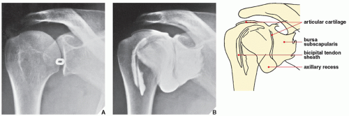 FIGURE 5.17 Arthrography of the shoulder. For arthrographic examination of the shoulder, the patient is positioned supine on the radiographic table, with the unaffected shoulder slightly elevated and the affected arm in external rotation with the palm up. (A) With the aid of fluoroscopy, a lead marker is placed near the lower third of the glenohumeral articulation to indicate the site of needle insertion. Under fluoroscopic control, 15 mL of positive contrast agent (60% diatrizoate meglumine or another meglumine-type contrast agent) is injected into the joint capsule. The usual study includes supine films of the shoulder in the standard anteroposterior (arm in the neutral position and in internal and external rotation) and the axillary projections. (B) A normal arthrogram of the shoulder shows contrast outlining the articular cartilage of the humerus and the glenoid and filling the axillary pouch, the subscapularis recess, and the bicipital tendon sheath. |
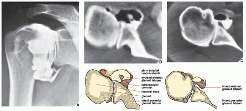 FIGURE 5.18 CT-arthrography—tear of the glenoid labrum. As the result of an auto accident, a 33-year-old woman sustained an injury to the right shoulder; she presented with pain and limitation of motion in the joint. Standard radiographs of the shoulder were normal. As injury to the cartilaginous labrum was suspected, doublecontrast arthrography was performed. Five milliliters of positive contrast agent and 10 mL of room air were injected into the joint capsule. (A) This arthrogram shows no evident abnormalities. The subscapularis recess, which is not opacified on this view, was shown later in the study to fill with contrast. (B) In conjunction with arthrography, a CT scan of the same shoulder was performed and clearly demonstrates avulsion of the anterior glenoid labrum, a finding not appreciated on the arthrographic study. Note that the avulsed fragment is surrounded by air and shows absorption of the contrast agent. (C) The normal appearance of the glenoid labrum is shown for comparison. |
GHL can be seen with the arm in the abduction and external rotation (ABER) position (see Fig. 5.22F). There are numerous imaging variations of the morphology of the cartilaginous labrum. The most common shape is triangular as illustrated in Figure 5.26. The second most common shape is round. The other morphologic variations include the flat labrum and the cleaved or notched labrum. On rare occasions, the anterior and posterior labrum may be absent. Furthermore, there are appearances resembling labral tears, such as undercutting of the labrum by hyaline cartilage, sublabral holes or recesses, and Buford complexes (see Fig. 5.82).
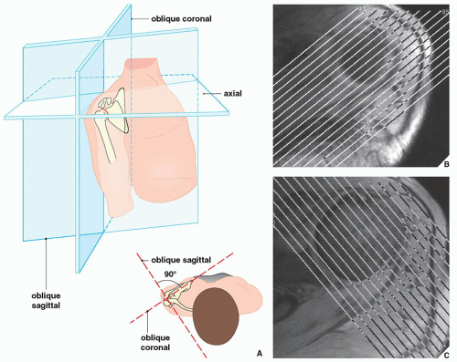 FIGURE 5.19 MRI of the shoulder. (A) Standard planes of MRI sections of the shoulder. (B) Oblique coronal sections are obtained parallel to the long axis of the scapula, perpendicular to the glenoid. (C) Oblique sagittal sections are obtained perpendicular to the oblique coronal sections, parallel to the glenoid. |
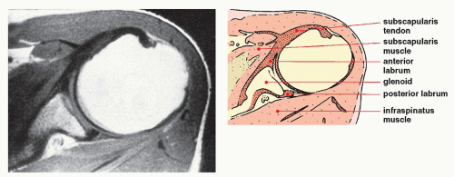 FIGURE 5.20 MRI of the shoulder. T1-weighted axial image of the left shoulder shows a normal subscapularis muscle and tendon and the infraspinatus muscle. The anterior and posterior glenoid labrum is also effectively demonstrated. |
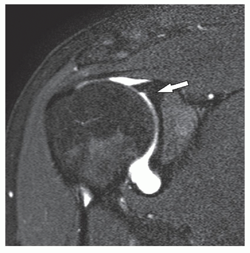 FIGURE 5.21 MRI arthrogram of the shoulder. T1-weighted fat-saturated oblique coronal image of the right shoulder following intraarticular injection of gadolinium demonstrates a normal supraspinatus muscle and tendon attaching to the greater tuberosity of the humerus. Note the excellent visualization of the superior labrum (arrow). |
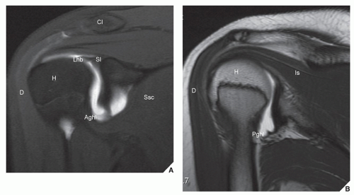 FIGURE 5.22 Normal MRI anatomy of the shoulder in the oblique coronal plane, oblique sagittal plane, and ABER position. Oblique coronal (A,B), oblique sagittal (C-E), and ABER (F) MRa images of the shoulder obtained with a 3 Tesla magnet of the same patient. (A) Oblique coronal T1-weighted fat-saturated image obtained through the anterior aspect of the shoulder demonstrates the supraspinatus tendon and the intracapsular portion of the long biceps tendon at its junction with the superior labrum. Note the AIGHL. (B) Oblique coronal T2-weighted image through the posterior aspect of the shoulder demonstrates the infraspinatus tendon and the PIGHL. (Continued) |
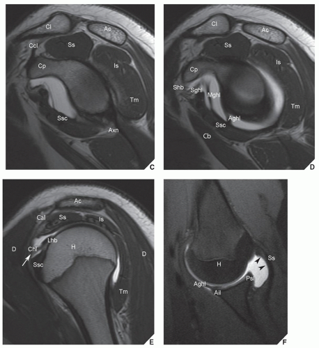 FIGURE 5.22 Normal MRI anatomy of the shoulder in the oblique coronal plane, oblique sagittal plane, and ABER position. Continued (C) Oblique sagittal T2-weighted image through the glenoid demonstrates the axillary nerve in the quadrilateral space. (D) Oblique sagittal T2-weighted image through the glenohumeral joint well depicts the SGHL and MGHL and the AIGHL. (E) Oblique sagittal T2-weighted image through the head of the humerus shows the relationship between the distal coracohumeral ligament and the long biceps tendon at the point where the tendon enters the joint capsule. The SGHL and the coracohumeral ligaments form the structure that surrounds the long biceps tendon (arrow) and provide stability of the tendon during arm motion. This structure is known as the sling or reflective pulley. (F) T1-wighted fat-saturated image in the ABER position shows the AIGHL, the anterior inferior labrum. Note the undersurface of the supraspinatus tendon (arrowheads). H, humeral head; Ac, acromion; Cl, clavicle; Cp, coracoid process; D, deltoid; Ss, supraspinatus; Is, infraspinatus; Ssc, subscapularis; Tm, teres minor; Shb, short head of the biceps; Lhb, long head of the biceps; Cb, coracobrachialis; Aghl, anterior band of the glenohumeral ligament; Pghl, posterior band of the inferior glenohumeral ligament; Sl, superior labrum and bicipitolabral junction; Mghl, middle glenohumeral ligament; Sghl, superior glenohumeral ligament; Chl, coracohumeral ligament; Ail, anterior inferior labrum; Psl, posterior superior labrum; Ccl, coracoclavicular ligaments; Axn, axillary nerve in the quadrilateral space; Cal, coracoacromial ligament. |
of this mixture is then injected into the shoulder joint using fluoroscopic guidance in a similar fashion as for conventional shoulder arthrography (see Fig. 5.17). Multiple pre-exercise and postexercise radiographic spot images are obtained in neutral position and in external and internal rotation of the arm. Subsequently, without delay, the patient undergoes MRI examination using similar scanning planes as for a conventional MR study. If glenoid labrum abnormalities are suspected, additional sequences are obtained in so-called ABER position.
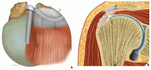 FIGURE 5.23 The cable and crescent. (A) Schematic demonstration of the configuration of the thickening of the deep fibers of the supraspinatus tendon or cable (arrows) viewed from above. The portion of the tendon between the cable and its insertion to the greater tuberosity of the humerus is called the crescent because of its shape (arrowheads). (B) Frontal view of the cable (arrow) and crescent (arrowheads). |
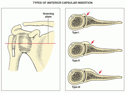 FIGURE 5.24 Capsule of the shoulder joint. Three types of anterior capsular insertion to the scapula. |
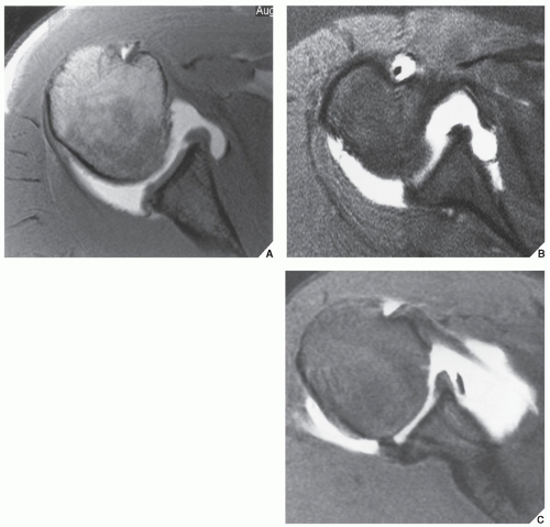 FIGURE 5.25 Capsular insertion to glenoid margin. (A) Axial T1-weighted image after intraarticular injection of gadolinium shows type I of anterior capsular insertion. (B) Axial fast spin-echo image with fat saturation and intraarticular gadolinium shows type II of anterior capsular insertion. (C) Axial T1-weighted image with fat saturation and intraarticular gadolinium shows type III of anterior capsular insertion. |
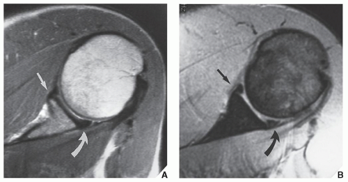 FIGURE 5.26 Fibrocartilaginous labrum of the glenoid. (A) Axial T1-weighted and (B) axial T2-weighted (multiplanar gradient-recalled [MPGR]) MR images show anterior (arrows) and posterior (curved arrows) labra as small triangles of low signal intensity. |
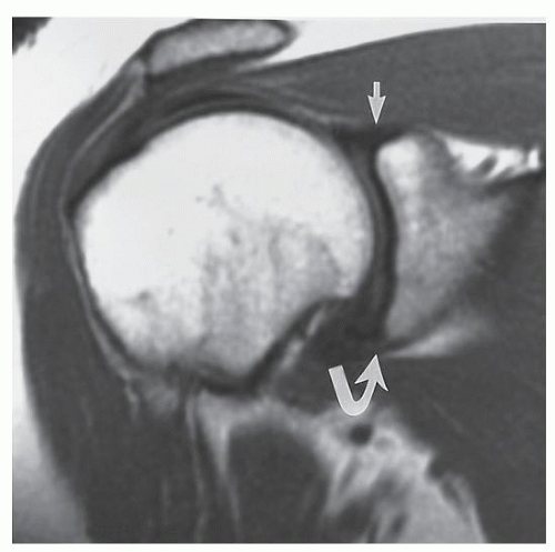 FIGURE 5.27 Fibrocartilaginous labrum. Oblique coronal T1-weighted fat-saturated MRI shows a superior (arrow) and inferior (curved arrow) labra labrum. |
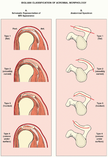 FIGURE 5.28 Variations of the acromial morphology. Schematic representation of morphologic variations of the acromion. (A) MRI appearance on oblique sagittal sections. (B) Appearance on anatomical specimen MRI, magnetic resonance imaging. |
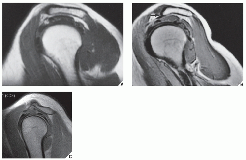 FIGURE 5.29 Morphologic variations of the acromion. (A) In the sagittal oblique plane, type II acromion shows a mild curved undersurface. (B) Type III acromion demonstrates a hooked undersurface (arrow). (C) Type IV acromion demonstrates a convex undersurface. |
TABLE 5.1 Checklist for Evaluation of Magnetic Resonance Imaging and Magnetic Resonance Arthrography of the Shoulder | ||||||||||||||||||||||||||||||||||||||||||||||||||||||||||||||||||||||||||||||
|---|---|---|---|---|---|---|---|---|---|---|---|---|---|---|---|---|---|---|---|---|---|---|---|---|---|---|---|---|---|---|---|---|---|---|---|---|---|---|---|---|---|---|---|---|---|---|---|---|---|---|---|---|---|---|---|---|---|---|---|---|---|---|---|---|---|---|---|---|---|---|---|---|---|---|---|---|---|---|
| ||||||||||||||||||||||||||||||||||||||||||||||||||||||||||||||||||||||||||||||
TABLE 5.2 Standard and Special Radiographic Projections for Evaluating Injury to the Shoulder Girdle | |||||||||||||||||||||||||||||||||||||||||||||||||||||||||||||||||||||||||||||||||||||||||||||||||||||||
|---|---|---|---|---|---|---|---|---|---|---|---|---|---|---|---|---|---|---|---|---|---|---|---|---|---|---|---|---|---|---|---|---|---|---|---|---|---|---|---|---|---|---|---|---|---|---|---|---|---|---|---|---|---|---|---|---|---|---|---|---|---|---|---|---|---|---|---|---|---|---|---|---|---|---|---|---|---|---|---|---|---|---|---|---|---|---|---|---|---|---|---|---|---|---|---|---|---|---|---|---|---|---|---|
| |||||||||||||||||||||||||||||||||||||||||||||||||||||||||||||||||||||||||||||||||||||||||||||||||||||||
TABLE 5.3 Ancillary Imaging Techniques for Evaluating Injury to the Shoulder Girdle | ||||||||||||||||||||||||||||||||||||||||||||||||||||||
|---|---|---|---|---|---|---|---|---|---|---|---|---|---|---|---|---|---|---|---|---|---|---|---|---|---|---|---|---|---|---|---|---|---|---|---|---|---|---|---|---|---|---|---|---|---|---|---|---|---|---|---|---|---|---|
| ||||||||||||||||||||||||||||||||||||||||||||||||||||||
Related posts:
 Radiologic Evaluation of Skeletal Anomalies
 Inflammatory Arthritides
 Benign Tumors and Tumor-like Lesions II: Lesions of Cartilaginous Origin
 Benign Tumors and Tumor-Like Lesions III: Fibrous, Fibroosseous, and Fibrohistiocytic Lesions
 Anomalies of the Upper and Lower Limbs
 Upper Limb III: Distal Forearm, Wrist, and Hand
Stay updated, free articles. Join our Telegram channel

Full access? Get Clinical Tree


