(1)
Biomedical Image Processing Lab, University of Minnesota, Minneapolis, MN, USA
Abstract
Many pure colors and grayscales tones that result from confocal imaging are not reproducible to output devices, such as printing presses, laptop projectors, and laser jet printers. Part of the difficulty in predicting the colors and tones that will reproduce lies in both the computer display, and in the display of unreproducible colors chosen for fluorophores. The use of a grayscale display for confocal channels and a LUT display to show saturated (clipped) tonal values aids visualization in the former instance and image integrity in the latter. Computer monitors used for post-processing in order to conform the image to the output device can be placed in darkened rooms, and the gamma for the display can be set to create darker shadow regions, and to control the display of color. These conditions aid in visualization of images so that blacks are set to grayer values that are more amenable to faithful reproduction. Preferences can be set in Photoshop for consistent display of colors, along with other settings to optimize use of memory. The Info window is opened so that tonal information can be shown via readouts. Images that are saved as indexed color are converted to grayscale or RGB Color, 16-bit is converted to 8-bit when desired, and colorized images from confocal software is returned to grayscale and re-colorized according to presented methods so that reproducible colors are made. Images may also be sharpened and noise may be reduced, or more than one image layered to show colocalization according to specific methods. Images are then converted to CMYK (Cyan, Magenta, Yellow and Black) for consequent assignment of pigment percentages for printing presses. Changes to single images and multiple images from image stacks are automated for efficient and consistent image processing changes. Some additional changes are done to those images destined for 3D visualization to better separate regions of interest from background. Files are returned to image stacks, saved and then printed to best reveal colors, contrast, details and features.
Key words
ColorizingImage processingGammaCMYKColocalizationImage modeVectorBandingRasterizationGaussianMedianSamplingQuantizationDialogue boxPaletteSaturationMidtoneCompressedConformanceProfile1 Introduction
The post-processing of confocal images has become a necessary practice for nearly every researcher using these devices. Except for those researchers who need to retain optical intensity of image features for subsequent measurement, and those who must show comparative optical intensities of two or more experimental conditions, confocal images simply do not contain color and grayscale values always amenable to output and these must be changed (1–3). These outputs include printing presses; inkjet (including wide format for posters), laserjet, thermal, dye sublimation, or photographic (such as the Fujix 3000) printers; LCD projection at meetings; screen displays for collaborators and other members within a work group, other software applications such as Word, Acrobat, and PowerPoint; or for 3D reconstruction software. For that reason, conformance of images to output is necessary in order to avoid obscuring important features, and to retain the look of the original without a loss in resolution along the way [4].
Clearly, in this discussion, it should be self-evident that local enhancement of the image be avoided (as was once done by dodging and burning when using photographic enlargers in a darkroom). Post-processing should only be applied to the entire image and, in the same way, to its experimentally related images. Outlining a feature in order to increase or decrease its optical intensity to the exclusion of other features, along with the inclusion of features (by cutting and pasting) that were not present in the original image, violates ethical practices [5]. The only arguable exception would include the elimination of artifact for 3D visualizations, as these obstruct the view of more important features.
Finally, the methods and procedures that follow provide the means to create a generic, “target” image. The thought is to balance every image so that it is ready for publication. From those images, then, subtle brightness changes can be made, or printing dimensions (and, possibly, image resolutions) can be set for other outputs, if that is deemed necessary. That approach is followed to simplify the imaging workflow, and to ensure that a standard is followed in workgroups. Most importantly, however, is that the final image will nearly always contain correct grayscale and color values—and reveal important features—no matter what the output.
2 Correct Colors
The operative word here is “correct.” Monitor to monitor variation (even when two monitors are the same make and model), will necessarily lead to differences in the rendition of color and contrast. For that reason, calibration tools can be bought for the monitor to more exactingly view color and contrast. These tools are relatively inexpensive at less than $200.00 (US), available at professional photography supply stores. Even when every monitor in a workgroup is not calibrated, a “proofing” monitor is best set aside for that purpose in a windowless room with dim, ambient lighting [6]. Not every Liquid Crystal Display, flat screen monitor is made alike. Most use Twisted Nematic (TN) technology as the cheapest alternative. TN technology results in poor displays (more at quickphotoshop.com). A better monitor can be paired with an inkjet or dye sublimation printer for making printed proofs as examples for how an image would reproduce when published. Protocol for making proofs can be found at http://www.quickphotoshop.com.
3 Good Images Before Photoshop
3.1 Viewing Images on the Confocal System
The design of confocal instruments always moves in the direction of making these easier to use. Part of that process includes colorizing images in order to view fluorochromes for easy identification. To clearly differentiate fluorochromes, three primary colors are typically used: green, red and blue. These are often used not only for display of the representative images on the computer screen, but software is also included to save what is a colorized image. In that manner, the object of making the confocal easier to use is fulfilled: the user can clearly view the different fluorochromes by color and these can be saved in color.
Yet, colorized displays can lead to poor decisions in regard to setting brightness levels, and unfortunate conclusions when interpreting the images. The color blue, for example, can be far more difficult to see, and that can lead to a user arbitrarily amplifying the signal beyond the dynamic range of the instrument. If a fourth display on the confocal system shows the combination of these three primary in a single window, the problem can then compound. The combination of pure red and green produces the color yellow, which appears bright; combinations of blue with red or green produce magenta or cyan, both dimmer than yellow and more uncertain when the two colors do not occur at equal intensities. Thus, any combination of colors with that of blue can again be interpreted poorly, and arbitrary adjustment of brightness is the natural tendency for users.
To make the setting of gain and black level on a computer similar among fluorochromes no matter what the color, the better option is to remove color altogether and view each fluorochrome as grayscale. Color images on a computer screen may look pretty, but the look also serves to confuse the eye. Images are best viewed in grayscale on the computer screen in order to make better decisions in regard to grayscale values (notwithstanding the use of LUT overlays to show saturation in the white and black ends of the dynamic range), and interpreting levels of fluorescence compared to background.
3.2 Use LUT Overlays in Order to Stay Within Detector’s Dynamic Range
Manufacturers of confocal equipment provide several LUTs for visualization, one of which displays colors in order to alert the user to “clipped” values. Clipped values include pixels that are at or greater than the dynamic range of the instrument, measured as a pure black at one end of the scale (pixel value of 0), and pure white at the other end (pixel value of 255 on an 8-bit scale, 4,095 at 12-bits and 65,535 at 16-bits). On an Olympus confocal system, a red overlay indicates clipped white values and a blue overlay indicates black, clipped values. Confocal settings must be changed in order to bring significant values within the dynamic range of the instrument (artifacts can be regarded as outside the range). Do not always adjust to remove all of the color overlay, however: randomly occurring spots of green or red are often a result of noise generated by the photomultiplier tube (PMT) and amplifier. When frame averaging is employed, these significantly brighter pixels become dimmer and fall into the dynamic range of the instrument.
By remaining within the dynamic range of the instrument, the darkest and whitest values will not contain untextured and featureless image information. In that way, all the image information is available later when post processing in Photoshop. The image may appear darker than what is desired, or the brighter features may not appear bright enough against the background, but, in either case, the image information lies in the digital file. If at all possible—when it does not interfere with the operation of confocal acquisition software (check with the manufacturer)—this monitor is calibrated.
4 Viewing Images in Photoshop
After the image is acquired within the dynamic range of the confocal instrument, then images can be edited in Photoshop. The first problem is, again, seeing the correct colors. Though the monitor may have been calibrated, the display of color jumps through yet another hoop: the display of color depends on its source and its destination. Taking the latter, the destination is assumed by Photoshop (in its default settings) to be within the limited range of colors used on the Web.
As far as the source of the colors, Photoshop can be alerted by the manufacturer of a color profile (tagged image) or not (untagged). Because confocal instruments produce untagged colors, the concern lies only with the destination of the image.
The act of displaying source and destination colors while in Photoshop is referred to as “Color Management.” The decision about how to view the colors while in Photoshop comprises the color editing space. So three possible categories of color are available for color management: the source colors, the editing color “space,” and the destination colors. Also included, are settings for grayscale press reproduction. These are all set in the “Color Settings” dialog box within Photoshop (Edit > Color Settings for Windows or for Macintosh OSX). What follows is a guide to decisions made in the “Color Settings” dialog box specific to confocal and fluorescence imaging for different working spaces (Fig. 1):

Fig. 1
Color settings dialogue box: working space is left at the default setting of sRGB IEC61966-2.1. The device independent, generic printing press settings depends upon the publisher’s country: here it is set to the USA. Color Management is turned off in this instance, but, when desiring to know the color space of the original file, these are turned on. Conversion Options appear when checking Advanced. The intent is set to Perceptual, what appears to be a good result for CMYK conversion of confocal images
4.1 RGB
Keep the default “sRGB IEC61966-2.1” (sRGB) setting. This is not generally the approach recommended by Photoshop experts, unless the colors are specifically destined for uploading to the Web [7]. In fluorescence microscopy, the colors are pure (saturated) and generally outside the range for printing press capabilities. In environmental photography, these saturated colors rarely exist, and so the approach is to see as many colors as possible, what would be result from choosing either Adobe RGB 1998 or ProPhoto Color for the color editing space. Color conversion, in particular to publication (though useful for other outputs, such as posters), is determined more accurately while retaining tonal ranges (when done correctly), when the default setting is retained (sRBG).
4.2 CMYK
Change this to the press that applies to the country in which a publication will be printed. For the USA, the recommended setting is “U.S. Web Coated (SWOP) v2”. In Europe and Japan it is “Euroscale Coated v2” and “Japan Standard v2,” respectively. Japan and Europe’s standard includes a dot gain that is less than in the USA, thus allowing for darker blacks to be printed along a greater range of colors. The difference is most notable for hard to publish colors, such as green. When colors are converted from the primary colors for light (red, green and blue) to the primaries for the printing press (Cyan, Magenta, Yellow, with the addition of a blacK channel: CMYK) the colors are set according to respective printing press conventions, or standards.
4.3 Gray
Set this the same as the monitor at Dot Gain 20 % as a default standard, unless author’s guidelines for particular journals state otherwise.
4.4 Spot
Dot Gain of 20 %. Generally, this is not used by scientists, as it addresses situations in which a specified color of ink is designated for printing on areas (spots) of a printed material.
4.5 Color Management Policies
For RGB, CMYK, and Gray
Generally, these are set to “Convert to Working …” When set to that policy, any image that opens, whether it comes with a profile or not, is treated as though it is in the current working (editing) space (sRGB).
Profile Mismatches
Generally, this, too, is unchecked, along with Ask When Pasting and Ask When Opening. Those who are more familiar with Color Management will want to be alerted, and these users will want the boxes left checked.
Advanced or More Options
Click on the Advanced checkbox (pre-CS) or on More Options (CS versions) to show Conversion Options. Set this engine to Adobe (ACE) for what is considered the best conversion engine for changing modes from RGB Color to CMYK Color and to LAB Color. Set the intent to Perceptual, when wishing to have colors that are converted to CMYK to have the same perceptual brightness levels. Uncheck Use Dither if images will be measured, because conversions will fill in colors to create smooth gradients. However, if images are for visualization, then consider leaving this box checked. Leave other settings at the defaults.
Other Photoshop settings, if not already determined, are listed below:
5 Photoshop Preferences
5.1 Memory
The use of computer hard disk memory should also be set. Photoshop requires ~3 times the hard disk space than the size of any single image file. That is required to complete many functions in Photoshop, as well as for clipboard space.
Under Edit > Preferences choose Plug-Ins and Scratch Disks (newer versions call this Performance). If more than one hard disk, or a partitioned drive exists, set the 1st, 2nd, etc., respectively, to the disk that has the greatest amount of free space, the next largest, and so on.
5.2 Transparency and Gamut, Display and Cursors
The following changes in Photoshop settings are based upon personal preference.
If the checkerboard pattern of squares that appears in images when working in Photoshop is confusing or annoying, under Transparency Settings set Grid Size to None.
If the diameter of Brush settings is desired so that the diameter of its size can be viewed (versus a crosshair), under Display and Cursors, choose Brush Size.
6 Photoshop Troubleshooting
Once preferences are set, if unfamiliar with Photoshop, some possible user troubles may interfere with completion of methods discussed in this chapter. While this chapter does not cover all possible troubles in Photoshop, the following are pointed out because of the frequency of their occurrence:
The “prohibited” symbol appears (red circle with diagonal line) or many options in the menus are grayed out:
1.
The image mode is incorrect. Change the mode from Indexed Color to RGB Color or Grayscale, depending on the final destination for the image.
2.
The image is 16-bit (versus 8-bit) and the version of Photoshop is pre-CS. Change from 16-bit to 8-bit, but only if the version is pre-CS. Photoshop CS versions are optimized for image processing 16-bit images. These images are better processed at the greater bit depth to allow for what is called “headroom.” In other words, the 16-bit image contains more gray values that can be eliminated, something that occurs at every step of image processing because of rounding errors for the greater glory of revealed features and output-corrected tones and colors.
3.
The text or symbol layer is selected. If the image is layered, such as what is done in Photoshop automatically when creating text and symbols, the layer may not be an image layer.
Note that the text and symbol layers are vector layers. These are not a collection of so many pixels (like images); instead, these are libraries from which printer drivers determine shapes. The conversion of a vector file to so many pixels is a process called rasterization. At that point, both text and symbols act like images insofar as these become a collection of pixels, and these display on the monitor much like these will print when viewed at about 100 % (the only real test of how text will print at this point lies in printing the images to an ink jet, photographic or dye sublimation printer: NOT a laser printer, as this may introduce artifacts into the lettering).
The prompt that reads as follows: “Warning: No pixels are more than 50 % selected. The selection edges will not be visible.” If that warning appears as a prompt, it means that a selection has been drawn too small, and probably by accident. It is easy, especially when first using Photoshop, to accidentally drag the mouse while on a selection tool (such as the marquee tool in the upper left of the Photoshop toolbox). If this warning appears, deselect the selection under Select > Deselect, or use the keyboard: Control/Command Key + D.
7 The Most Important Window in Photoshop: Info Palette (Fig. 2)

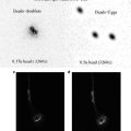
Fig. 2
Using sampling eyedropper tool and info box: (from right to left ) First image shows two sampling tool markers on the darkest and the brightest positions (determined visually and iteratively by checking values in the Info box while moving cursor over the image, and then clicking at these positions with the sampling eyedropper tool). The second image shows placeholders taken by sampling positions in the Info box, labeled #1 and #2. Typical readouts are shown: the first readout, which takes the upper left position in the Info box is set to Grayscale and this indicates the percentage of ink laid on paper were the image to be printed (values from 0 to 100 %). The second readout is set to 8-bit, RGB Color so that 0–255 tonal values are shown. By clicking on the circled eyedropper tool, units of measurement for readout values can be changed by choosing from a drop down list
In order to determine effects upon images on an objective basis while referring to numeric readouts, a palette is opened for viewing at all times. This palette is not opened by default, and so it is opened by choosing it under Window in the menu (Window > Info).
All of the pixels that make up the image contain tonal values assigned to each pixel. These can be viewed along several different units of measurement: for purposes of confining the units of measurement to a single scale (thus making these easier to recall) these are displayed as RGB Color, 8-bit (0–255 discrete tonal levels). This reading can be selected for grayscale images (as opposed to the default unit of measurement in K:, or “percent of ink deposited were it printed to paper”) so that these values remain uniform across all types of images. For color images, the 8-bit values are read for each channel: an RGB Color image contains three channels: red, green and blue. Note that 16-bit values can also be chosen as the unit of measurement, but readouts are, confusingly, in the 15-bit range (0–32,768) as a result of carryover from earlier Photoshop programs (these values are not the intrinsic values of the image, however). Thus, readouts in 16-bit values are not referred to in methods.
The small eyedropper tool in the Info box can be clicked on to reveal a drop down list. Choose RGB Color from this box (or RGB Color, 8-bit in CS versions).
This box has the added advantage of displaying values at specific positions on the image, up to a total of four. These are called sampling points or markers, and these are purposefully created at desired positions on your image, typically at the whitest significant point of your image and at the blackest point. Values at those positions can be then be tracked while making contrast, brightness, and, possibly, gamma adjustments.
To prepare to mark these points, do as follows:
1.
Click on the eyedropper tool in the toolbar or type the letter “I.”
2.
On the options bar, below the menu, click on arrowhead adjacent to Sample Size. Choose 3 × 3 Average for most images and 5 × 5 Average if the image is excessively noisy (grainy). The idea is to sample an average of several pixels rather than only one, as a single pixel would be less likely to garner a representative value.
To sample an area of the image, do the following (see Fig. 3):

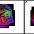
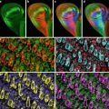
Fig. 3
Channel Mixer dialogue box and example image: Top, darker, blue colored image on right shows the image were it simply converted to Grayscale using Image > Mode > Grayscale: note the loss of brightness. The image on the right below the darker image and the dialogue box settings to the left show the grayscale image converted first by using Channel Mixer and then converted to grayscale using Image > Mode > Grayscale. Note the retention of brightness values. Image courtesy of Martin Wessendorf, Ph.D.
1.
Click on the eyedropper tool in the toolbar or type the letter “I.” Choose the Sample Eyedropper tool, or hold down the Shift key with the standard eyedropper.
2.
Click on desired part of the image. That will nearly always mean the brightest significant (non-artifact) point(s) on the image, and the darkest point(s). The Info box will expand to display pixel values at these locations and a marker will be left that is visible, but will not print.
3.
To remove sampling marks, either click Clear button on submenu when the eyedropper tool is active, or hold down the control/command key and click and drag marker off the image area.
8 Working with Images in Photoshop
Here are typical steps that are required in Photoshop when working with fluorescent images:
8.1 Opening Image: Indexed Color to Grayscale or RGB Color
Many confocal images from older systems are saved as indexed color with 256 levels of gray or color assigned to the image. Before subsequent methods can be used, the image must be converted to Grayscale or RGB Color, depending on the final intent.
Under Image > Mode, choose Grayscale or RGB Color.
8.2 Converting 16-Bit to 8-Bit
As mentioned above, it is always best to preserve 16-bit depth of a potential 65,536 gray values (though images could have been rescaled to 16-bit from 10-, 12- and 14-bit ranges). Keep images at 16-bit, if possible, when using Photoshop CS and greater when working on the image. When the image is readied for output, or when using pre-CS versions of Photoshop, convert the image from 16- to 8-bits/channel:
Under Image > Mode, choose 8-Bits/Channel.
8.3 Resetting Colorized Single Fluorescent Images to Grayscale
If an image from confocal software is saved as a colorized image (versus an image with levels of gray), the result will be an image that is impossible to publish without a loss of brightness in the highlights, a shift in color and a general dimming of the image. Of the three primary colors used for colorizing (red, green and blue), only the color red contains the greatest possibility for matching what is seen on the computer screen to output. That is because the range of hues (gamut) of available colors for light (RGB) do not always overlap with the range of colors available for printing with pigments (CMYK) at desired intensities. Even when colors are simply displayed on a computer screen, the color green dominates as brightest, red appears dimmer than green and blue is often so dim that it is hard to see detail.
It follows, then, that a colorized image saved from confocal software must be altered in color so that it can conform to output and be viewed correctly on the monitor. That saved image may be re-colorized by choosing from a panel of colors in certain software packages in order to get a better fit for output, or it can be returned to a grayscale image and then colorized again in Photoshop.
Note that the colorized image cannot be returned to grayscale by simply changing the mode in Photoshop to grayscale. A change in mode to grayscale is heavily weighted by the green channel (versus the red or blue channels). Because of that, red and blue images will lose their inherent brightness levels! These images must be changed to grayscale using Channel Mixer in Photoshop. This is critical for those wishing to measure optical intensity values from colorized confocal images.
8.4 Channel Mixer Procedure: Returning a Colorized Image to Grayscale to Preserve Brightness (Fig. 3)
1.
Under Image > Adjust(ments), choose Channel Mixer.
2.
 Confocal Imaging of Butterfly Tissue
 Confocal Imaging of Fluorescently Labeled Proteins in the Drosophila Larval Neuromuscular Junction
 Vital Imaging of Multicellular Spheroids
 Imaging Tools for Analysis of the Ureteric Tree in the Developing Mouse Kidney
 Evaluating Confocal Microscopy System Performance
 Laser Scanning Confocal Microscopy: History, Applications, and Related Optical Sectioning Techniques


Check the Monochrome box. The Output Channel indicator will change to Gray, indicating a grayscale image.
Related posts:
Confocal Imaging of Butterfly Tissue
Confocal Imaging of Fluorescently Labeled Proteins in the Drosophila Larval Neuromuscular Junction
Vital Imaging of Multicellular Spheroids
Imaging Tools for Analysis of the Ureteric Tree in the Developing Mouse Kidney
Evaluating Confocal Microscopy System Performance
Laser Scanning Confocal Microscopy: History, Applications, and Related Optical Sectioning Techniques
Stay updated, free articles. Join our Telegram channel
Full access? Get Clinical Tree
