Vessel injected
Injector settings
ml/s
ml
Aortic arch
20
25
Common carotid artery (CCA)
8
12
Subclavian artery
6
15
Internal carotid artery (ICA)
6
8
External carotid artery (ECA)
3
6
Vertebral artery
6
8
3D angiogram in internal carotid artery
3
20
Another feature to keep in mind is the rise: a “rate rise” in cerebral angiography refers to a progressive acceleration of contrast over the first second of the injection. The linear rate rise feature is especially useful when a catheter is near the origin of a vessel and a sudden injection of contrast may result in recoil of the catheter proximal outside of the desired vessel. The PSI setting of the injector refers to the maximum pressure (pounds per square inch) that the injector will generate while injecting the contrast.
Cervico-Cerebral Angiography
Biplane angiography is nowadays the standard of care for cervico-cerebral angiograms and allows for two planes to be acquired simultaneously with a single contrast injection, limiting the total amount of time and contrast needed to complete the study.
Projections
Standard projections are illustrated in the figures; the x-ray detector has a limited space, and as such, the space needs to be optimized. Standard arch projection is a left anterior oblique that opens the view of the aortic arch. To better visualize the origin of the vertebral artery, a Towne’s view is necessary, given the origin of the artery in the superoposterior aspect of the subclavian artery. The Towne’s view is obtained angulating the detector 30–40° cranially aligning the petrous ridges below the superior rim of the orbits.
Standard neck arteries views are the straight frontal and lateral projections (Fig. 1). If a single plane is used, an ipsilateral oblique frontal view is preferable.
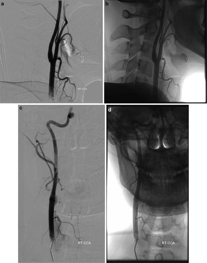
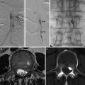
Fig. 1
Standard angiographic views for the CCA bifurcation: lateral, subtracted and unsubtracted (a, b) and straight frontal subtracted and unsubtracted (c, d)
Before obtaining the cranial images, careful evaluation of the alignment of the head along the long axis of the detector should be checked. In the standard frontal (PA) view of the internal carotid injection, the petrous ridges are aligned with the lower third of the orbits (Figs. 2a–e and 3a–f). In the lateral projection, careful evaluation of the alignment of the orbital roof and of the external auditory canals is needed (Figs. 2f–j and 3g–j). While for a CCA injection, the outer skull has to be included on the field of view, for an ICA injection the positioning of the detector has to be adjusted just to cover the inner skull. For vertebral injection intracranial views, both a frontal and Towne’s views are needed, while for the lateral projection, the C1 vertebra coverage needs to be checked (Figs. 4 and 5). Special views are obtained in particular situations: for example, to better see the ICA cavernous segment, the communicating segment, or the middle cerebral artery branches, a Haughton view may be obtained; in order to position for this view, the x-ray tube needs to be tilted caudally towards the shoulder of the side of interest. To better visualize the ICA bifurcation or the anterior communicating artery complex, an ipsilateral transorbital oblique is recommended. To memorize all the useful projections for the different vessels can be cumbersome; the best way to obtain the best views is to create a 3D virtual map of the cerebral vasculature in thier mind and use this virtual map to guide the best projection based on the orientation of the vessel of interest.
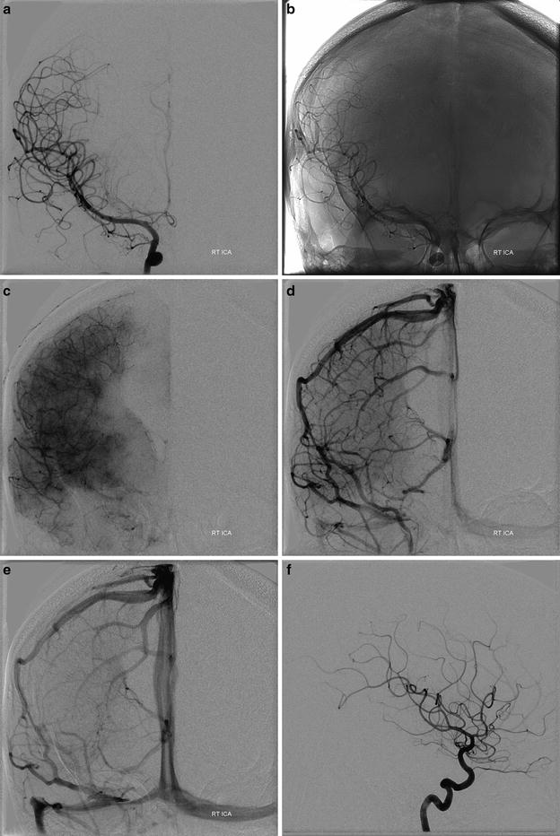
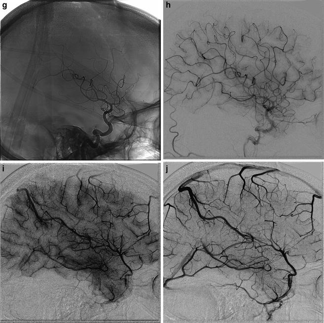
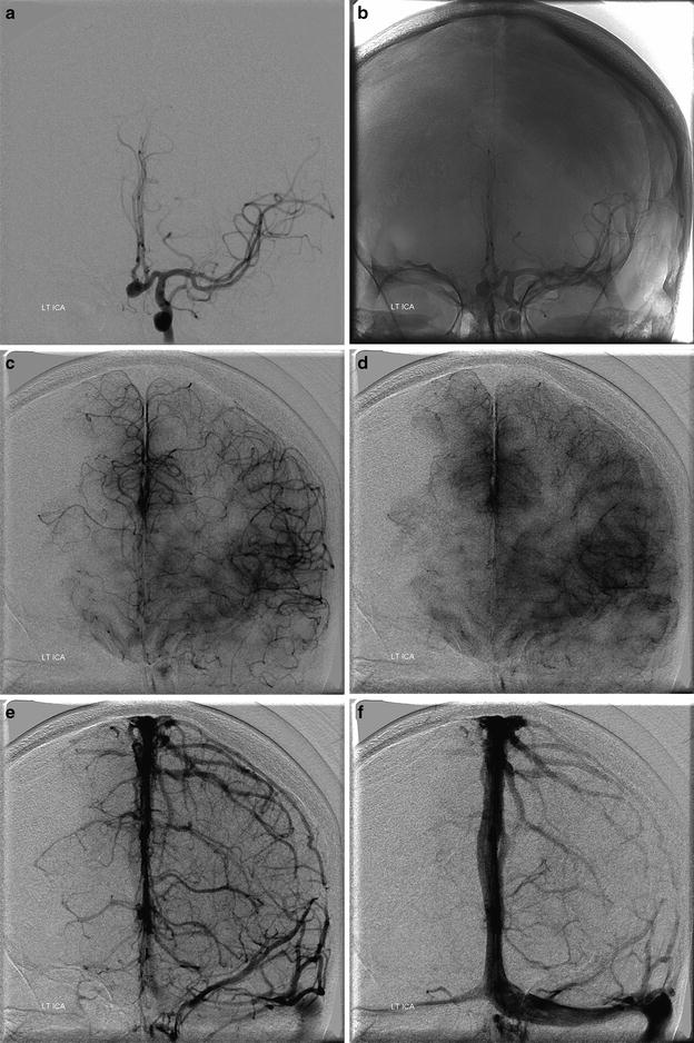
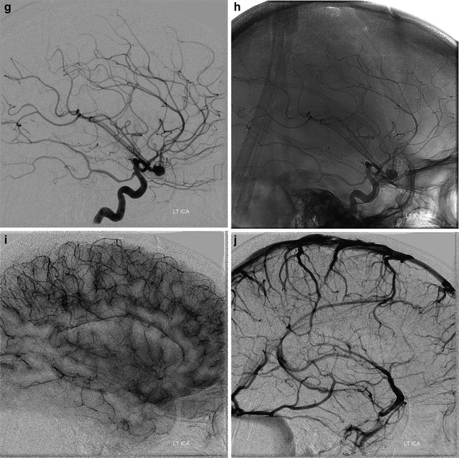
Fig. 2
Right ICA injection. In the standard frontal view of the internal carotid injection, petrous ridges are aligned with the lower third of the orbits. (a–e) Frontal projection of right ICA in early arterial – subtracted (a) and unsubtracted (b), – capillary (c), early venous (d), and late venous (e) views. (f–j) Lateral projection in early arterial – subtracted (f) and unsubtracted (g) –, capillary (h), late capillary/early venous (i), and early venous (j) views
Fig. 3


Left ICA injection. In the standard frontal view of the internal carotid injection, petrous ridges are aligned with the lower third of the orbits. (a–e) Frontal projection of left ICA in early arterial – subtracted (a) and unsubtracted (b) – early capillary (c), late capillary (d), early venous (e), and late venous (f) views. In the lateral projection (g–j) the alignment follows the orbital roof and the external auditory canals: early arterial – subtracted (g) and unsubtracted (h) – capillary (i), and late venous (j) views
Related posts:

Stay updated, free articles. Join our Telegram channel
Full access? Get Clinical Tree
