1. Pitfalls due to GS artifacts
Due to transducer position
Anisotropy
Bone pseudodefect
–
Due to interaction of US beam to the tissues
Attenuation
Shadowing
Reverberation
Mirror
Side lobe/grating lobe
Cartilage interface
Enhancement through transmission
–
Associated with velocity errors
2. Pitfalls due to Doppler artifacts
Mirror
–
Reverberation
3. Pitfalls due to human error (GS and Doppler)
Drop out
Machine incorrect adjustment
Transducer incorrect handling
Insufficient anatomy knowledge
4. Pitfalls due to machine error (GS and Doppler)
Piezoelectric crystals damage
Transducer’s fibers damage
Pitfalls Due to GS Artifacts
Artifacts Due to Transducer Position
Anisotropy , according to Wikipedia [14] , is the property of being directionally dependent, as opposed to isotropy, which implies identical properties in all directions. US, especially musculoskeletal, is an anisotropic technique—in abdominal US the only tissue exhibiting anisotropy is the renal tissue [7]. Anisotropy is an artifact that appears in all the situations where the US beam is not strictly perpendicular to the examined tissue for ensuring maximal reflectivity. Anisotropy appears mostly in tendons; muscles and ligaments can exhibit it at a lesser extent. Nerves do not show anisotropic properties [9]. Any tissue containing parallel linear fibers can exhibit anisotropy. Due to highly organized structure of collagen fibers inside tendons, these are highly anisotropic structures. A tendon becomes anisotropic mainly at the point of its insertion where it follows the round shape of the bone epiphysis. Any angle deviation from 90° decreases the tendon echogenicity, making it resembling the muscle in appearance and obscures structural details; at higher deviation angles, the echogenicity will decrease even more [9, 11]. The presence of a hypo-echoic area near a tendon’s insertion must lead to anisotropy considering before making a tendon tear diagnosis. The most important places to encounter anisotropy are: bicipital tendon inside the groove, quadriceps, and Achilles tendons at their insertion. Patellar tendon (also known as patellar ligament) has a straight direction, so it is usually visualized without anisotropy at both insertions (Figs. 2.1, 2.2, 2.3, 2.4, and 2.5) .
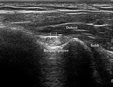
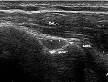
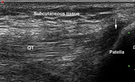
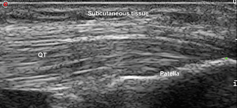
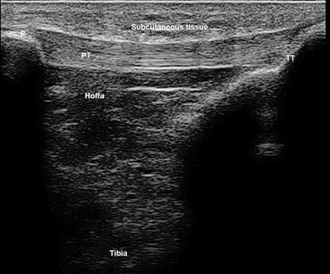

Fig. 2.1
Transverse view of bicipital tendon (arrows) inside the groove. The transducer is perpendicular to the tendon. SubS subscapularis tendon

Fig. 2.2
Transverse view of “empty” bicipital groove (arrows). The transducer is not perpendicular to the tendon. SubS subscapularis tendon

Fig. 2.3
Longitudinal view of quadriceps insertion on patella. The transducer is not parallel to the fibers at the insertion. QT quadricipital tendon. Arrow: anisotropy at insertion

Fig. 2.4
Longitudinal view of quadriceps insertion on patella. When angulating the transducer it becomes parallel to the fibers at insertion and anisotropy disappears. QT quadricipital tendon

Fig. 2.5
Longitudinal view of patellar tendon. Due to its straight trajectory, no anisotropy appears at insertions. P patella, TT tibial tuberosity, PT patellar tendon
Tips to Overcome
Gently tilting the transducer until it becomes perpendicular to the structure makes anisotropy disappear, and the tendon’s fibers appear intact. Sometimes it is enough to slightly move the patient’s joint, like in hand flexors evaluation. Knee flexion also makes anisotropy of quadriceps insertion disappear. Tendon tears should always be visualized in two perpendicular planes and they remain unchanged when tilting the probe. Dynamic evaluation of the tendon’s movements can also help ruling out tears .
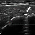
Bone pseudodefect is another artifact linked to the position of the probe in relation to the bone contour. When the beam touches the bone in a semi tangential way, the reflected echoes will have a different direction compared to the normal return and will not be detected on the screen. There will be no captured image in that area, so it will falsely look like a break in the bone contour. This artifact must be carefully differentiated from various pathologic cortical defects, which appear on two perpendicular planes and usually have a floor that may be visualized on the US image. Bone pseudodefect is frequently visible in the elbow area, at the coronoid fossa evaluation (Fig. 2.6).
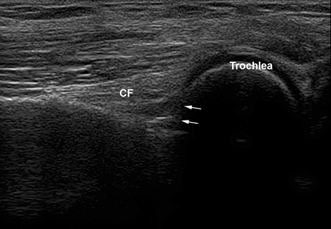

Fig. 2.6
Longitudinal view of the anterior elbow. Bone pseudodefect artifact is seen because of the transducer position, semitangential to the bone (arrows). CF coronoid fossa
Tips to Overcome
Same as for anisotropy—gently tilting the probe for changing the angle of the beam toward the bone will make the defect disappear .
Artifacts Due to Interaction of Beam with Tissues
US beam interacts with tissues according to their specific characteristics. Generally, the waves are attenuated inside tissues because of reflection, scattering, refraction, or absorption processes, but sometimes their transmission might be enhanced. US attenuation is 80 % due to absorption, a small reminder of the beam being reduced by reflection, refraction, diffraction, and dispersion [15]. Different tissues have different attenuation coefficients (calculated at 1 MHz). The values are listed in Table 2.2 [4, 16] .
Table 2.2
Attenuation coefficients and US speed for selected tissues at 1 MHz
Material | Attenuation coefficient | US speed (c)m/s |
|---|---|---|
Water | 0.0002 | – |
Air | 40 | 330 |
Fat | 0.5–1.8 | 1450 |
Soft tissue | 0.3–0.8 | 1540 |
Bone | 13–26 | 4080 |
Attenuation Artifacts
A brief description of the physical phenomena leading to beam attenuation would increase their understanding .
Reflection of the beam appears at the boundary between two types of tissues with different densities; as a consequence, the propagation speed of waves will be different too. The property of tissues that involves density and speed of waves is called acoustic impedance, marked as Z (Z = speed × density of the tissue). The final US image is the result of multiple reflection processes. At the boundary between two tissues with highly different acoustic impedance, the reflection of the waves will be strong, so a strong echo will be generated. This situation is particularly encountered at the interface between air/bone and soft tissues. At the interface between soft tissue and air, 99 % of the waves are reflected, so no image will appear behind this. A particular situation illustrating this is the presence of an air gap between the transducer and the skin. To avoid that, a thick, uniform layer of gel must be applied on the transducer. Air is, though, a strong attenuator of the beam. Other strong attenuators are bone and calcifications. Behind these structures the attenuation will be so high that a shadow will appear, suggesting US waves do not penetrate that structure because they are all reflected. If the adjacent tissues have similar acoustic impedance, no echoes are generated. Most of the soft tissues have close values of acoustic impedance, so very few waves are reflected, most of the beam passing further to deeper structures [10].
Refraction is a change of US beam direction at interfaces between media with small differences in acoustic impedance (fat/muscle). Because of this phenomenon, real structures may appear in false locations. The degree of direction changing is influenced by the difference of impedance and also by the angle of the beam, which may easily be adjusted by tilting the transducer.
Scattering of the beam occurs when the reflecting surface is very small compared to the wavelength of US, and echoes are reflected through a wide range of angles, consequently reducing their detected intensity. When the beam encounters a number of small interfaces, comparable to the wavelength, a particular type of scattering appears, called diffusion. This is the situation of the fat or fibrous tissue (Fig. 2.7). Scattering and diffusion of the waves must be considered for correctly interpreting the echogenicity of small parts nodules .
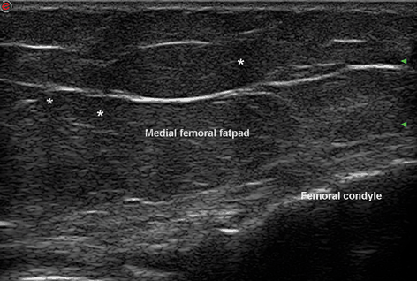

Fig. 2.7
Longitudinal view of the medial fat pad of the knee in an obese patient. Scattering and diffusion of US create shadows (asterisks) and allow a fair visualization of the structures below (femoral condyle). US ultrasound
Shadowing
Shadowing is the lack of US image behind structures like air or bone. Because of this artifact, bones and organs containing air like digestive tube cannot be visualized with US. Different types of shadows are produced by air and by bone—while shadow behind the bony structures and calcifications is uniform and homogeneous, called “clean,” shadow behind the air is called “dirty.” Dirty shadow has a heterogeneous aspect, with mixed areas of hypo- and anechogenicity. Sometimes dirty shadow may appear behind bony structures with a large radius of curvature, like humeral head [5]. A particular example of shadowing is represented by skin calcifications in dermatomyositis or scleroderma patients—the continuity of calcium deposits forms a continuous line immediately under the skin with no echoes behind it (Figs. 2.8 and 2.9). When the shadow is generated by a superficial structure, it may run over a deeper structure in the image and mimic pathology like tendon tear. A shadow may appear behind wood fragments as foreign bodies in subcutaneous tissue or deeper [5].
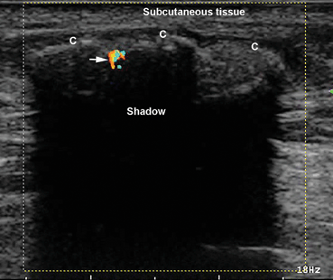
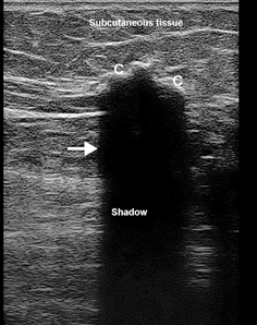

Fig. 2.8
Longitudinal view of the thigh of a young patient with juvenile dermatomyositis. A compact layer of calcifications are seen just under the skin. A “clean” shadow is covering all structures behind. The inflammatory aspect of calcifications, which were painful, is shown by the incomplete mirror Doppler artifact—the only two parts seen in the image are the bone and the mirror (arrow). C calcium deposits

Fig. 2.9
Transverse view of the gluteal region in a scleroderma patient. A big calcification (C) is seen in the subcutaneous tissue. A “clean” shadow appears behind (arrow)
When a strong reflecting structure like a calcification is very small compared to the width of the main US beam, the posterior acoustic shadowing will be eliminated. This situation may occur in case of small calcifications inside a fluid collection. Awareness of this artifact, called beam width, will ensure proper diagnosis of calcium deposits, even without shadow (Figs. 2.10 and 2.11). Sometimes focus adjustment strictly in the area of interest will remove the artifact [5] .
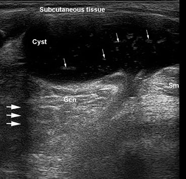
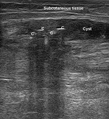

Fig. 2.10
Transverse view of the medial part of popliteal fossa. A Baker cyst is seen with small white deposits inside without shadow—calcifications exhibiting beam width artifact (small arrows). Also, a lateral shadowing phenomenon appears at the cyst margin (large arrows). Gcn gastrocnemius muscle and tendon, Sm semimembranosus tendon

Fig. 2.11
Calcifications (C) in a small Baker’s cyst with mixed echogenicity. Each calcification, though very small, has its own separate shadow, covering tissues behind
At the margins of a structure with different acoustic impedance compared to the tissue around it and with a highly curved surface (tendons’ margins, cyst, etc.), an artifact called lateral shadowing (or refraction shadowing) appears. After reflection of the beam, marginal waves get also refracted at the edges of the structure, therefore no sound beam is returning to the probe; as a consequence, a shadow near each lateral border of the structure may appear (Fig. 2.12). A particular case of refraction at the edges is represented by superficial varicosities (Fig. 2.13). Refractile shadowing also appears in case of tendon full-thickness tears, and sometimes it might be the only US sign of the tear.
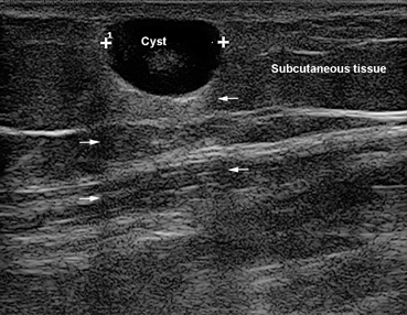
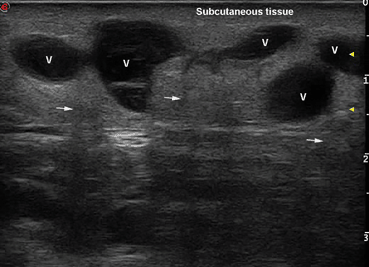

Fig. 2.12
Subcutaneous cyst, showing lateral shadows due to refraction (arrows)

Fig. 2.13
Superficial varicosities (v) in subcutaneous tissue showing lateral shadowing (arrows)
Tips to Overcome
Shadowing cannot be overcome, but it is of great help in interpreting US pathology. However, this type of artifact may look like another pitfall, caused by machine damage, presented below, so careful distinction is needed .
Reverberation
Reverberation is an attenuation artifact generated by structures with two parallel surfaces, both highly reflective. Examples may be the prostheses used by orthopedists (shoulder, knee, hip) or a needle/biopsy device (Figs. 2.14 and 2.15). In such structures, US echoes will experience repeated reflections between the two surfaces of the prosthesis and the bone or between the two facets of the needle before going back to the transducer. Because of this mechanism, only the first echo will be properly located on the screen; the others will be displayed far away, and will appear deep in the image. Finally, the image on the screen will consist of multiple linear echoes spaced at equal distance, posterior to the first echo. Each echo will be weaker than the precedent one, due to attenuation. Bone exhibits reverberation artifact too; very often, bone contour appears again on the screen below the real one. Reverberation is also encountered in gynecologic US [17].
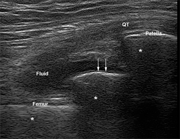
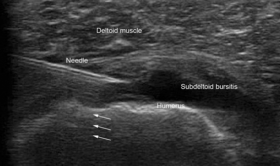

Fig. 2.14
Longitudinal view of the suprapatellar recess of a knee with prosthesis. Between patella and femoral cortical lines, another hyperechoic line is depicted—the prosthesis image (arrows). All three lines have reverberation artifacts behind them (asterisks). QT quadricipital tendon

Fig. 2.15
Transverse view on the anterior shoulder. An anechoic image (subdeltoid bursitis) is shown under deltoid muscle with a needle inserted in it. Reverberation artifact of the needle is shown behind it (arrows)
The dirty shadowing behind air bubbles is a particular type of reverberation. An example is the image representing a corticoid injection inside a cyst. Together with the corticoid, air from the syringe is injected, and it immediately rises in the upper part of the cyst, leaving a dirty shadow/reverberation artifact behind it .
A particular type of reverberation is the comet tail artifact, which accompanies the intrusion of a foreign object with very different acoustic impedance compared to the tissue around it. Comet tail artifact can appear behind a metallic prosthesis or behind glass. It has a characteristic shape, widening distally or proximally. Comet tail artifact is useful when marking the place of an injection by placing a needle between the skin and the transducer (Fig. 2.16). The artifact will indicate the precise location for the injection.
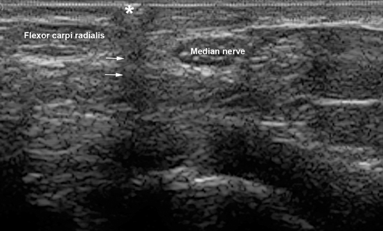

Fig. 2.16
Transverse view of the median nerve at the wrist. A needle (asterisk) is placed on the skin under the transducer. A comet tail artifact (arrows) is seen below the needle, indicating the injection place
In the same category, the ring-down artifact appears when a very thin layer of fluid is trapped between air bubbles. In some publications, these last two types of artifacts are considered totally different [4], while in others they are considered the same [16].
Reverberation artifact may appear on the screen before even starting US examination because of the intense reflection of waves at the interface between the transducer and air. This artifact disappears when the transducer is in direct contact with the skin through a layer of gel (Fig. 2.17) .
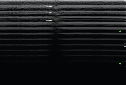

Fig. 2.17
Reverberation artifact before starting US examination. Many hyperechoic parallel lines equally spaced are seen. There is no gel on the transducer, except for a very small part, in the middle, which leaves a trace on the whole image (arrows). US ultrasound
Tips to Overcome
The last type is the only reverberation artifact that can be overcome. The others cannot be eliminated, as they are caused by the type of tissue involved. Sometimes this type of artifacts can be helpful, like in case of the characteristic appearance of air/gas present together. If not intraluminal, the aspect combining air and gas might be a characteristic US sign of an abscess collection [5]. Based only on reverberation artifacts, a whole new US area has developed—pulmonary US (details are given below). New type of machines with harmonic imaging can reduce a little reverberation artifacts [9].

