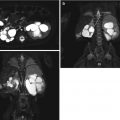
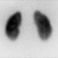
Fig. 2.1
(a) An example of an A-mode scan. The received echo amplitude is plotted against time of transmission which is proportional to the depth. (b) In B-mode, the received echoes are displayed as a series of dots of varying brightness creating a two-dimensional image. (c) In M-mode, a diagram is created by graphing the received echoes on a plot of depth versus time (From Whittingham [2]. Reprinted with permission from Elsevier Limited)
A-mode (amplitude mode) ultrasound obtains echoes along a specified depth axis. After propagation through the tissues, the echoes that are returned are graphically displayed with the amplitude of the echo versus time. This appears on the screen as spikes along a horizontal line. This mode is particularly useful in situations that knowledge of the depth of the interface is desired and can be used therapeutically [1].
B-mode (brightness mode) ultrasound converts the received echoes into a series of dots of varying brightness, creating a two-dimensional grayscale image [2]. Early B-mode scanners required a patient to be placed in an immersion bath. In 1962, three men—Joseph Holmes, William Wright, and Ralph Meyerdirk—developed the compound contact B-mode scanner, revolutionizing ultrasound imaging in health care. Several more advances in B-mode scanners were developed in the 1970s.
When real-time capability was developed in B-mode, this became the dominant form of medical sonography. Real-time B-mode obtains information to create two-dimensional images that are used for the majority of medical imaging. For a given plane, multiple piezoelectric crystals are arrayed, and sound waves are sent and received and are then integrated to produce a grayscale image. The spectrum of grayscale brightness that is displayed for each received echo corresponds to the amplitude of the wave. The beam is rapidly and continuously reproduced and received to provide a dynamic, real-time image [1].
M-mode (motion mode) ultrasound obtains a series of B-mode signals, which are then displayed along a time axis, allowing for evaluation of the motion of a structure [1]. Therefore, at specific known depths from the transducer, the echoes are translated as motion of that structure. Short segments of the data can be stored digitally and played back instantly. Most common uses for this mode would be for analyzing movements of the heart or in obstetrics to isolate the beating heart of a fetus.
Basic Concept of Ultrasound
The ultrasound wave is produced by applying short burst of alternating electrical current to special crystals known as piezoelectric crystals, housed in the transducer, also known as a probe (Fig. 2.2). The electric current causes heating and polarizing of the lead atoms that are loosely bound within a crystal matrix. The crystal will then expand and contract, converting electrical energy into an acoustic wave. This phenomenon of converting electric energy into a pressure/sound wave energy and vice versa is known as the piezoelectric effect. Today these elements are commonly made from ceramic materials [3, 4].
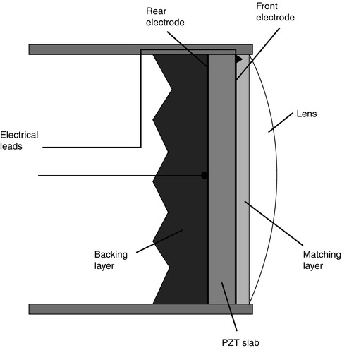

Fig. 2.2
The basic components of an ultrasound probe (From Whittingham [2]. Reprinted with permission from Elsevier Limited)
The frequency of the wave produced is dependent on the pulses of electrical current and the plate thickness of the piezoelectric material. Typical frequencies of ultrasound waves, i.e., transducers used in urological exams, are between 2.0 and 15 MHz, which are above the limits of human hearing. These acoustic waves are transmitted into the patient by the transducer, with the aid of a coupling gel, when the transducer is placed on the body. The efficiency of this process is improved by the presence of an impedance barrier, the rubber surface present on the transducer. These sound waves can then be reflected, refracted, scattered, or absorbed by the body.
The ultrasound wave is affected by the physical characteristics of the tissue through which it is propagated and then reflected. As the wave travels through the body, ultrasound echoes are received by the transducer. These echoes are then converted back into electric energy, which are then processed and translated into an image on the screen.
The Principles and Physics of Ultrasound in the Body
The ultrasound wave is a mechanical wave. Its movement through tissue causes oscillation of the tissue in a longitudinal direction, propagating the mechanical wave. As the ultrasound wave moves through different types of tissues, i.e., density, the elements of the tissue will oscillate higher or lower in relation to its ambient state, without net motion.
Frequency
The number of waves or pulses occurring in time, i.e., seconds, and is expressed in Hertz (Hz). Wavelength (λ) describes the physical space that one pulse length occupies. Frequency and wavelength are inversely related because of their relationship to velocity (velocity = frequency × wavelength). A higher frequency will result in a shorter wavelength and vice versa. For ultrasound imaging, the general ultrasound tissue velocity or speed is given as a constant (c) at 1,540 m/s [5, 6].
Assuming constant velocity (c), the depth (D) at which the interface occurred can be calculated as D = c/2 x (time from pulse generated to echodetection). The number 2 reflects that the wave traveled from the transducer to a point and the sound wave traveled back from that point, prior to being received by the transducer [4].
Amplitude
The maximum height or size that the wave travels in the positive or negative direction. The clinical significance of the wave amplitude is that it corresponds to the energy contained in the mechanical wave. Energy is equal to the amplitude squared. In clinical terms of the grayscale image, the amplitude affects the pixel brightness so that a greater amplitude wave produces pixels that are brighter [4].
Reflection
There are two types of wave reflections that occur and are received by the transducer that demonstrate clinical significance, specular echo and scatter echo.
When the transducer sends and receives a wave that is reflected off a smooth/flat surface, perpendicular to the angle of the moving sound wave, the echo is considered a specular or mirrorlike echo. The angle of reflection will be equal to the angle of incidence keeping with Snell’s Law. This type of echo, the specular echo, is characteristically reflected with the highest intensity strength and directionality. Specular echoes are seen from the linings of hollow viscera, blood vessels, fascial planes, organ capsules, skin, and gas or bone surfaces. To help correct for the speckling characteristic seen in some tissues, a technique called compounding can be used. Compounding sends sound waves into the tissue from multiples angles. Sending compound waves enables better image contrast by combining specular echoes, so they are more likely to be detected which results in minimizing speckling.
When sound waves are reflected off surfaces with irregularities, and the irregularities are similar in size to the wavelength of the sound wave, the energy of the wave is dispersed in all directions. This is known as scatter. The scatter echo returning to the transducer is therefore weaker and typically only detectible if several of the scattered wavelets are superimposed to produce an additive effect. Scattering accounts for the textured appearance of a tissue type, which is a result of an interference pattern, and is referred to as speckling. This property gives parenchyma such as the liver or testicles their characteristic appearance and makes them distinguishable from other structures. However, it should be noted that there is a spectrum between specular echoes and scattering with most tissues demonstrating properties that fall between the two extremes.
Rarefaction
It should also be stated that when a sound wave pulse is sent from the transducer, the wave does not necessarily propagate in a uniform and linear manner. Rather, the wave pulse becomes distorted as it travels through the tissue medium with some areas of the pulse having higher frequency components or harmonics corresponding to areas with increasing density of the medium. A portion of the wave would then travel faster than the rarefaction component of the wave which travels slightly slower. Rarefaction artifacts can occur therefore at the interface of two types of tissue as the angle of the sound wave is no longer linear. This can be seen at tissue interfaces such as fat and soft tissue or at soft tissue fluid interfaces. In the latter, the part of the beam that does not pass through the fluid is less intense that those traveling through the fluid structure. The difference in distortion is dependent on the initial sound wave intensity. The higher the acoustic power, the stronger the harmonics, and therefore a greater difference between the weaker sections of the wave frequency can occur. Stronger areas of the beam are typically located in the central section of the wave beam. Additionally, since it takes a few cycles to ramp up the intensities, frequencies are also weaker within the first few millimeters of tissue penetrated. Machines that filter out and select for a particular frequency produce a better image with improved contrast and counteract this distortion.
Absorption
The energy from the sound wave stimulates the tissue particles to move, enabling the sound wave to be transmitted as an acoustic vibration. If the tissue particles move in a cohesive and organized manner, then the vibration is transmitted efficiently. However, if the particle movement becomes chaotic and disjointed, then the sound wave will become chaotic, and the energy from the sound wave will be lost and converted into heat. When sound wave energy is lost by this method, it is referred to as absorption. Absorption is greater when the percentage of large particles in the tissue is increased; thus, the tissue has a greater viscosity. Similarly, absorption is dependent on the frequency of the sound wave with greater absorption occurring with higher frequencies. Per 1 cm depth of sound wave penetration, 1 dB is lost per 1 MHz transmitted. Thus, the higher the frequency, the more decibels are lost per centimeter of tissue causing the potential depth of penetration to be decreased. Since the speed of the sound wave traveling through soft tissues is constant, the time delay of the reflected sound wave can be used to calculate the depth of reflected image.
Attenuation
Anytime energy is lost and not returned to the transducer it is referred to as attenuation. Absorption is only one type of attenuation and was explained in the previous paragraph. Another type of attenuation occurs when the sound wave is reflected or refracted in such a way that the wave is unable to be returned in the same plane as to be detected by the receiving transducer. When a sound wave crosses an interface between two different tissues, some of the wave’s energy is reflected. The degree or proportion of the energy in the wave that is reflected is dependent on the change in the tissue density across that interface, also known as the impedance mismatch.
Typically, only a small percentage of reflection occurs with interfaces of similar tissues (<10 %). However, a tissue-gas interface leads to almost complete reflection of the wave and with tissue-bone or tissue-calculus interfaces resulting in almost 60–75 % of the wave being reflected. When this degree of reflection occurs, an acoustic shadow is then created. The acoustic shadow prevents visualization of structures deep to this interface as there had been almost complete reflection of the sound wave. The dark band is caused as the tissue absorbs the sound wave faster than the background, and the area deep to the highly attenuating region appears dark. Fat, gas, and calcifications are especially associated with shadowing (Fig. 2.3). Calcifications that are smaller than 5 mm will demonstrate shadowing when higher-resolution transducers are used. Similarly, aggregates of fine calcifications can shadow if their size and density is sufficiently high. Another type of shadowing is known as edge shadows or edge artifact that appears as fine, dark lines extending deep to curved surfaces. These are commonly seen in isolated cysts or at the edge of a testis (Fig. 2.4).
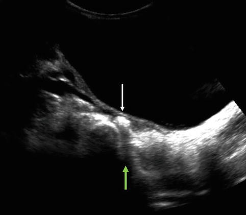
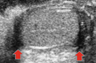

Fig. 2.3
Arrow pointing to a calculus (white arrow) in the distal right ureter demonstrating the phenomenon known as shadowing (green arrow)

Fig. 2.4
Edge artifact is demonstrated on both the superior and inferior edges of this testis (red arrows)
In contrast, there can be increased transmission when waves are less attenuated, such as transmission of sound waves through a simple cyst. The posterior wall of the cyst can artificially appear hyperechoic. This is known as through transmission (Fig. 2.5).
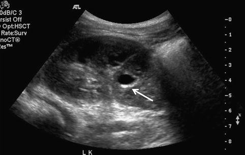

Fig. 2.5
Cyst in left kidney mid pole demonstrates the phenomenon of through transmission (arrow)
Acoustic Impedance
This occurs at the interface of two tissue types, i.e., tissues with different densities. Part of the wave will be reflected and part will continue longitudinally through the tissues. The more different the tissues at the interface, the greater the contrast of the image obtained versus those of similar tissue density.
Acoustic Intensity
This is defined as the power per unit area of the ultrasound pulse. The more ultrasound waves concentrated in a smaller area, the more the intensity of the sound waves and the more detailed the image. The larger the cross-sectional energy, the less intensity per unit area, the lower the amplitude.
Resolution
This is defined as the ability to distinguish two objects that are in close proximity to one another. There are two types of resolution, axial resolution and lateral resolution, which are important in generating the image.
Axial resolution is the ability to differentiate between objects that are in the direction of the traveling wave or in front of one another. This property is dependent on the frequency of the sound wave. A higher frequency results in better image resolution due to the shorter sound wavelength, allowing for differentiation of objects that are close to each other. However, higher frequencies have more rapid attenuation as it passes through tissues, and resolution therefore is limited by depth.
Lateral resolution is the ability to identify two separate objects that are next to each other. This characteristic is dependent on both the focus width of the ultrasound wave beam and the transducer. The narrower beam of focus for a particular depth enables better lateral resolution. For a larger beam of focus, i.e., scanned field of view, the acoustic intensity is less resulting in less amplitude and less resolution. Remember also the average velocity of a wave in human tissues is given as constant at 1,540 m/s, and a change in frequency equals a change in wavelength [5, 6]. This ultimately affects the depth of resolution. At higher frequencies, shorter wavelengths are produced allowing better resolution of more superficial structures. For deeper structures, longer wavelengths are required with lower frequencies resulting in poor resolution. Typically for imaging structures such as the testicles or pediatric kidney, a higher frequency such as >7.5 MHz is used. But, for deeper structures such as the adolescent or adult kidney, 3.5–5 MHz is preferred.
Stay updated, free articles. Join our Telegram channel

Full access? Get Clinical Tree


