Fig. 1
(a) Brachytherapy setup, showing the TRUS probe, guiding template, stepper, C-arm, and radio-opaque fluoroscope tracking fiducial (FTRAC). (b) A sample axial TRUS image of the prostate with implanted seeds. (c) A sample X-ray image showing the seeds
Seeds can deviate from their planned positions for many reasons, including prostate motion and deformation [2], prostate swelling due to insertion trauma [3], needle deflection [4], and seed migration. Therefore, the real distribution of the implanted seeds never perfectly matches the plan. The resultant suboptimal dose distribution can lead to under-dosing of the cancerous gland or overdosing of the organs at risk. Consequences are complications such as sexual and urinary dysfunction, rectal ulceration, and cancer recurrence.
The treatment quality is assessed traditionally using CT one day or up to 4 weeks after the operation, when modifications to the treatment are difficult or impossible. Accurate localization of the implanted seeds in real time during the operation would enable the physician to detect the under-dosed regions and predict the regions with high chance of over-radiation while the patient is still on the operating table. In this case, optimal dose coverage could be achieved before the patient leaves the operating room. Real-time seed localization followed by dose calculation and modification, a process called “Dynamic Dosimetry”, has been a topic of extensive research during the past decade [5, 6]. In addition to providing real-time evaluation of the procedure, dynamic dosimetry can simplify the quantitative postoperative dosimetry by replacing the postimplant CT.
Since TRUS is the main imaging modality during prostate brachytherapy, an extensive body of research has been dedicated to seed localization in ultrasound. Methods such as processing the B-mode images [7], singular spectrum analysis [8], analyzing the radio-frequency signal [9], trans-urethral ultrasound [10], Doppler ultrasound imaging of magnetically vibrated seeds [11], and vibroacoustography [12] have been tried. However, ultrasound-only seed localization methods have not shown the necessary robustness for clinical application. Ultrasound (US) images are of relatively low quality when the tissue is implanted with metallic seeds. For example, distal seeds (with respect to the US probe) can be located in the shadow of proximal seeds. Some seeds are oriented at an angle with respect to the incoming ultrasound beam that causes reflection of the beam away from the probe, rendering them invisible. US images are also rife with seed-looking artifacts caused by calcifications and air bubbles (see Fig. 1). In fact, it has been shown that even careful manual identification of the seeds in B-mode images cannot result in reliable dosimetry [13].
A commercially available method for an approximate dynamic dosimetry is to manually identify the seeds on the sagittal ultrasound image as they are ejected from the needle. Although this method has shown successful results [5, 14], it cannot account for seed motion after deposition. Therefore, the final resting place of the seeds remains unknown and the actual dose is not known with great accuracy.
A promising alternative for ultrasound-only seed localization and dosimetry is multimodality integration of ultrasound and fluoroscopy. C-arm fluoroscopy is widely used in brachytherapy practice for projection visualization of the seeds. Several X-ray images taken from different angles can be used to reconstruct the seed positions in 3D. However, C-arm fluoroscopy images have almost no soft-tissue contrast (see Fig. 1). Since for dosimetry the seeds must be localized with respect to prostate boundaries, seeds localized with C-arm fluoroscopy should be registered to ultrasound.
In this chapter, we introduce a fully automatic and practical system and workflow for reconstruction of the seeds in 3D using C-arm fluoroscopy and registering them to ultrasound images.
Dynamic Dosimetry Using Ultrasound-Fluoroscopy Registration
A possible workflow for dynamic dosimetry using ultrasound-fluoroscopy registration consists of the following. (1) During the operation, when needed, a TRUS volume of the prostate region is acquired. The TRUS volume can be reconstructed from axial images taken during the retraction of a tracked TRUS probe from the prostate base to apex (see Fig. 2a, b). Alternatively, the volume can be reconstructed from sagittal images acquired during a rotational sweep. (2) Following US imaging, at least 3 C-arm fluoroscopy images are acquired at different C-arm positions (see Fig. 2c). Conveniently, these images are taken by rotating the C-arm in a cone around the anterior-posterior (AP) axis of the patient. The TRUS probe is retracted before C-arm imaging to avoid occlusion of the seeds. (3) The X-ray images are processed for seeds and fiducials that are used for C-arm pose computation. (4) The seeds are reconstructed in 3D by solving a matching problem that finds the correspondence between different seed projections of a particular seed in different images (Fig. 2d). (5) Finally, the reconstructed seeds are registered to the TRUS volume and used for implant evaluation and dosimetry (Fig. 2e). Based on the dosimetry information, the under-dosed and likely-to-be overdosed regions can be identified and the rest of the implant plan can be modified accordingly.
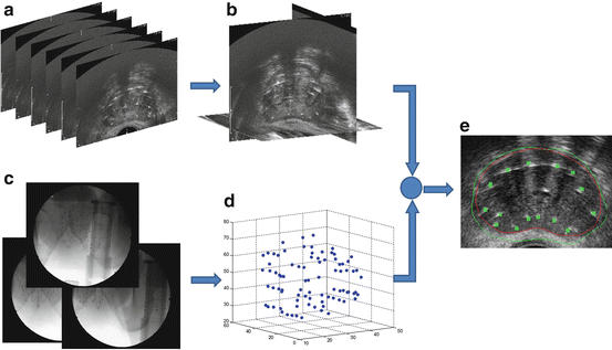

Fig. 2
The workflow for dynamic dosimetry using ultrasound-fluoroscopy registration. (a) Several axial slices of TRUS images. (b) A reconstructed TRUS volume. (c) Three X-rays acquired at different angles. (d) Reconstructed seeds in 3D space. (e) A sample axial slice of TRUS volume overlaid with the registered seeds (green squares), prostate contour (red), and 100 % isodose line (green)
Reconstruction of Seeds in 3D Space
An essential component in our dynamic dosimetry system is the reconstruction of seeds in 3D space from several X-ray images taken from different angles. Two main methods have been devised for seed reconstruction in 3D—digital tomosynthesis and matching-based methods. In the former, the background is removed from the X-ray images and the seed projection regions are back-projected toward the corresponding X-ray sources. The corresponding back-projections for each seed intersect in the seed location. Digital tomosynthesis inherently solves the matching problem and recovers hidden seeds [15–20]. Since tomosynthesis-based reconstruction methods only require separation of the seeds from the background in a binary image; hence, explicit localization of the seed projection centers in the images and declustering are not necessary. However, tomosynthesis-based methods suffer from false positives and are relatively time-consuming. In the matching-based seed reconstruction methods, a seed is localized in 3D space by triangulation. In order to do so, the correspondence between the seed projections in different X-ray images should be known. Since this correspondence is not known, the matching problem and the reconstruction are solved together. For matching-based reconstruction methods, seed projection centroids should be identified in the images. However, in every image there can be several overlapping or hidden seeds, where the seed centroids cannot be reliably identified. Recent studies have engineered seed reconstruction methods that can solve the matching problem and recover the hidden seeds [21–25]. Compared to tomosynthesis-based methods, matching-based seed reconstruction requires fewer X-ray images.
Most reconstruction methods assume accurately known pose of the C-arm during image acquisition obtained through external tracking of the C-arm device or accurate geometry of radiotherapy simulators. External tracking of a C-arm device is not always practical and radiotherapy simulators are not available in every brachytherapy operating room. As a solution, seeds have been used as fiducials to improve an initial estimation of C-arm pose during seed reconstruction [19, 26–29]. In our work, we use reduced dimensionality matching for prostate brachytherapy seed reconstruction with automatic pose correction (APC-REDMAPS) [25, 29]. This is a fast, practical, and robust matching-based method that is able to concurrently estimate the pose of the images as well as solve for the matching problem despite presence of hidden seed projections.
Our seed reconstruction method requires seed projection centroids to be segmented in the X-ray images. In addition, a relatively accurate C-arm pose is required for fast and successful reconstruction. The C-arm pose can be calculated using a fluoroscope tracking fiducial, named FTRAC, introduced by Jain et al. [30] that consists of 2 ellipses, 3 parallel lines, and 9 beads as shown in Fig. 3. The FTRAC can be mounted on the guiding template used for prostate brachytherapy. The C-arm pose can be recovered after segmentation of the projections of the FTRAC in the X-rays with the tracking accuracy of 0.33° in rotation and 0.56 mm in translation [30]. In the following, we describe the algorithms for segmentation of the fiducial and seed projections in the X-ray images as well as our method for solving the matching problem and pose correction.
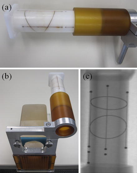

Fig. 3
(a) The fluoroscope tracking fiducial (FTRAC). (b) FTRAC mounted on the guiding template. (c) An X-ray image of FTRAC, showing the projections of the ellipses, lines, and beads
Seed and Fiducial Segmentation in X-Ray Images
Our X-ray processing algorithm is responsible for automatic segmentation of the FTRAC ellipses, lines, beads as well as the center of seed projections in the image without a manually selected region of interest [31]. In addition, if some seed projections are overlapped, the image processing can detect and separate them into their constituent projections. We assume that the X-rays are corrected for image distortions caused by the image intensifier. The correcting function parameters can be calculated preoperatively using a calibration device which is also used to identify the C-arm calibration parameters. We also assume that the seeds and FTRAC are fully visible in the C-arm images and the FTRAC image does not overlap with the seed projections (Fig. 4). This can be achieved by limiting the C-arm rotation to a ±10° cone around the patient’s AP axis. The image processing algorithm requires that the FTRAC appears on the right side of seeds and in an almost vertical position in the X-ray image. Mounting the FTRAC on the grid as shown in Fig. 3b satisfies this requirement (see Fig. 4 for an example).
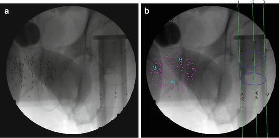

Fig. 4
The result of seeds and FTRAC segmentation on a clinical image. (a) The original image. (b) Segmented seeds, ellipses, beads, and lines (shown by numbers). Magenta dots indicate single seeds are marked by magenta dots and separated overlapping seeds by cyan circles
Fiducial Segmentation
The X-ray processing starts with segmenting the FTRAC lines and beads. The FTRAC specific design, in which the beads are positioned on the top of the three parallel lines, is taken into account for simultaneous segmentation. The algorithm starts with generating a binary image by applying a top-hat by reconstruction operation using a disk-shaped structuring element on the complemented X-ray image followed by the Otsu thresholding [32]. The region properties of the connected components including their area, eccentricity, solidity, and location are used to distinguish beads from seeds. As the beads are located on parallel lines, the Hough transform is applied to the image and the strongest three parallel lines in an almost vertical orientation on the right side of the image are selected. The line positions are further refined and then used to localize the beads in the image [31].
Following the detection of the FTRAC beads and lines, a pipeline of morphological image filters including top-hat operation and image opening, thresholds, and edge thinning algorithms are applied to the images to detect the edges of the ellipses. Then, knowing the position of the beads, the candidate edges for the two ellipses are separated. Finally, an ellipse detection algorithm based on random sample consensus (RANSAC) is employed to fit two ellipses to the detected edges. For more details on the ellipse detection we refer the readers to [31].
Seed Segmentation
Once the FTRAC is segmented, the X-ray processing can continue onto seed segmentation without interference from the fiducial. The pipeline continues with generating a binary image by applying a top-hat by reconstruction operation using a disk-shaped structuring element on the complemented X-ray image followed by the Otsu thresholding. To reduce false positives, connected components within the region of the FTRAC or outside the densest seed cloud region of connected components are removed.
Most of the remaining connected components correspond to single seed projections, although some may correspond to multiple overlapping seed projections. A metric based on the rearrangement of Beer’s law can serve as an estimate of the number of seed projections within each connected component:


(1)

Here, I x(x,y) is the X-ray image intensity at position (x, y), I 0is the incident X-ray intensity, z is the axis orthogonal to the image plane along the line of projection, and V is the volume of the object(s) imaged. Therefore, a calculation of  can serve as a metric for estimating the number of seed projections within each connected component, since the resulting value is a constant μV for single seed projections and n times the constant μV for n seed projections. For more details on the metric, we refer the readers to [31].
 can serve as a metric for estimating the number of seed projections within each connected component, since the resulting value is a constant μV for single seed projections and n times the constant μV for n seed projections. For more details on the metric, we refer the readers to [31].
The coordinates of the seed projections can finally be calculated through application of the k-means clustering algorithm [33], which partitions data into a user-defined number of clusters. For this case, the input data are the pixel coordinates within a specific connected component weighted by intensity, and the number of clusters is the now computed metric for the connected component. The output partition separates any overlapping seeds and the centroid of each partition results in the desired seed projection position.
Solving the Matching Problem
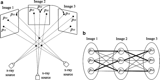
As mentioned, we need at least three X-ray images taken at different angles to reconstruct the seeds. Without loss of generality and for the sake of simplicity, we assume that we have only three X-rays. Assume that the images are processed so the seed projections are segmented in the images. To start with, let’s assume that the C-arm poses (the relative positions and orientations of the X-ray images in 3D space) and the correspondences between the seed projections in different images are known (see Fig. 5 for an example). For each of the corresponding seed projections p i1, p i2 and p i3 in images 1, 2 and 3, respectively, there is a line L ij , j ∈ {1,2,3} that connects that projection to its corresponding C-arm source position r j , j ∈ {1,2,3}. Then, the reconstructed seed position s i is the point with minimum aggregate distance from these lines and is calculated as:
![$$ {s}_i={\left[{\displaystyle \sum}_{j=1}^3\left(I-{v}_{ij}{v}_{ij}^{\prime}\right)\right]}^{-1}{\displaystyle \sum}_{j=1}^3\left(I-{v}_{ij}{v}_{ij}^{\prime}\right){r}_j, $$](/wp-content/uploads/2016/03/A303895_1_En_23_Chapter_Equ2.gif)
where, v ij is the unit vector along L ij , I is the identity matrix, and (.)′ denotes the transpose of a matrix or a vector. We define the “reconstruction accuracy” as the root mean square distance from the reconstructed seed to L ij ’s [25], which is zero in ideal case with known image poses.
![$$ {s}_i={\left[{\displaystyle \sum}_{j=1}^3\left(I-{v}_{ij}{v}_{ij}^{\prime}\right)\right]}^{-1}{\displaystyle \sum}_{j=1}^3\left(I-{v}_{ij}{v}_{ij}^{\prime}\right){r}_j, $$](/wp-content/uploads/2016/03/A303895_1_En_23_Chapter_Equ2.gif)
(2)

Fig. 5
(a) Schematic diagram of reconstruction of three seeds from their projections in 3 X-ray images. The correspondence between the seeds and different projections are shown. (b) All possible matching solutions between the seed projections in different images. Each edge in this figure has a weight equal to the reconstruction accuracy. The correct matches for the simple case shown in (a) are indicated by thick edges
In the problem of seed reconstruction for prostate brachytherapy, the correspondence between seed projections is not known. In addition, there are hidden seed projections in the images. Therefore, seed localization and the correspondence problem should be solved jointly. This problem can be formulated as a combinatorial optimization problem:

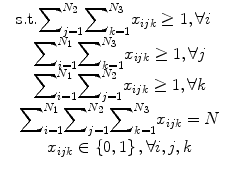
where N is the total number of implanted seeds, N 1, N 2, N 3 are the numbers of segmented seed projection centroids in images 1, 2, 3, respectively. c ijk is the cost of matching the seed projection i from image 1 with seed projection j from image 2 and seed projection k from image 3. The variable x ijk is equal to 1 if seed projections i in image 1, j in image 2, k in image 3 are selected as a match, i.e., originate from the same physical seed, and equal to 0 otherwise. The matching cost c ijk is a function of C-arm pose rotation Φ = (ϕ 1,ϕ 2,ϕ 3) and translation t = (t 1,t 2,t 3). We use the reconstruction accuracy as the matching cost [25, 29]. Since x ijk is binary, this combinatorial optimization problem becomes a binary integer programming problem. The inequalities in (4) guarantee that each seed projection is selected at least once. Seed projections are allowed to be selected more than once to recover the hidden seeds. The equality constraint assures that the number of reconstructed seeds is equal to the number of implanted seeds.

(3)

(4)
Due to the large number (around 100) of implanted seeds during a brachytherapy session, the above mentioned problem is of large dimensionality and cannot be solved fast enough for practical purposes. Therefore, APC-REDMAPDS reduces the dimensionality of this matching problem through a pruning algorithm [25]. Lee et al. has shown that over 99 % of the variables in (3) can be eliminated [25]. Moreover, the dimensionality reduced binary programming in (3) can be solved using linear programming with relaxed fractional constraints in near real time. If the C-arm poses are known relatively accurately, the reduced linear programming renders a binary solution that is global optimum of (3). However, if the C-arm pose is not known very accurately, the solution may not be binary and, if rounded, may not be globally optimal. Therefore, APC-REDMAPS is designed to solve the matching problem and improve the pose estimations, iteratively.
Automatic Pose Correction
In order to solve the matching problem 100 % correctly, the pose of the C-arms should be known precisely, which is not the case in clinical practice. However, the linear programming approach described above has shown to correctly recover most of the seed correspondences for image pose errors up to 5° in rotation and 10 mm in translation [25].
If the C-arm poses are precisely known, the lines that emanate from corresponding seed projections intersect at a single point. Therefore, if the reconstructed seed is projected back on the images, the distance between the projection of the reconstructed seed and the corresponding segmented seed projection on each image should be zero. However, in the presence of C-arm pose errors, there are errors between the projections of the reconstructed seed and its segmented seed projections on the images. We use the term “projection error” for this error. The projection error is employed within APC-REDMAPS to improve the pose estimation accuracy. The matching and pose improvement problems are solved iteratively until convergence.
Let s i W = [s ix W ,s iy W ,s iz W ,1]′ represent the position of the i th seed in the 3D homogeneous world coordinate system. The projection of this seed on the j th image can be calculated in the image homogeneous coordinate system as:
![$$ {p}_{ij}=\left[\begin{array}{cccc}\hfill f/{\sigma}_x\hfill & \hfill 0\hfill & \hfill {o}_x\hfill & \hfill 0\hfill \\ {}\hfill 0\hfill & \hfill f/{\sigma}_y\hfill & \hfill {o}_y\hfill & \hfill 0\hfill \\ {}\hfill 0\hfill & \hfill 0\hfill & \hfill 1\hfill & \hfill 0\hfill \end{array}\right]\left[\begin{array}{cc}\hfill \boldsymbol{R}\left({\phi}_{j1},{\phi}_{j2},{\phi}_{j3}\right)\hfill & \hfill {\mathbf{t}}_j\hfill \\ {}\hfill \underset{\bar{\mkern6mu}}{0}\hfill & \hfill 1\hfill \end{array}\right]{s}_i^W, $$](/wp-content/uploads/2016/03/A303895_1_En_23_Chapter_Equ5.gif)
where the left matrix is the projection matrix that consists of the C-arm focal length f, the origin of the image (o x , o y ), and the pixel spacings (σ x , σ y ), all of which can be preoperatively calibrated. The right matrix is the C-arm pose matrix which is defined by the C-arm rotation and translation parameters. Equation (5) renders the x–y coordinates of the seed projection as ![$$ {\left[\begin{array}{cc}\hfill {p}_{ij}^x\hfill & \hfill {p}_{ij}^y\hfill \end{array}\right]}^{\prime } $$](/wp-content/uploads/2016/03/A303895_1_En_23_Chapter_IEq2.gif) . Then, the projection error for seed i in image j can be calculated as:
. Then, the projection error for seed i in image j can be calculated as:
![$$ \varDelta {e}_{ij}=\left[\begin{array}{c}\hfill {p}_{ij}^x\left({\boldsymbol{\Phi}}_i,{\mathbf{t}}_i\right)\hfill \\ {}\hfill {p}_{ij}^y\left({\boldsymbol{\Phi}}_i,{\mathbf{t}}_i\right)\hfill \end{array}\right]-\left[\begin{array}{c}\hfill {q}_{ij}^x\hfill \\ {}\hfill {q}_{ij}^y\hfill \end{array}\right], $$](/wp-content/uploads/2016/03/A303895_1_En_23_Chapter_Equ6.gif)
where, ![$$ {\left[\begin{array}{cc}\hfill {q}_{ij}^x\hfill & \hfill {q}_{ij}^y\hfill \end{array}\right]}^{\prime } $$](/wp-content/uploads/2016/03/A303895_1_En_23_Chapter_IEq3.gif) denote the position of the segmented seed centroid in the image. A linear approximation of Δe ij with respect to the pose error can be written as:
denote the position of the segmented seed centroid in the image. A linear approximation of Δe ij with respect to the pose error can be written as:
![$$ \varDelta {e}_{ij}=\mathbf{J}\ \left[\begin{array}{c}\hfill \begin{array}{c}\hfill \varDelta {\phi}_{j1}\hfill \\ {}\hfill \varDelta {\phi}_{j2}\hfill \\ {}\hfill \varDelta {\phi}_{j3}\hfill \end{array}\hfill \\ {}\hfill \begin{array}{c}\hfill \varDelta {t}_{j1}\hfill \\ {}\hfill \varDelta {t}_{j2}\hfill \\ {}\hfill \varDelta {t}_{j3}\hfill \end{array}\hfill \end{array}\right]=\mathbf{J}\varDelta {E}_j $$](/wp-content/uploads/2016/03/A303895_1_En_23_Chapter_Equ7.gif)
![$$ {p}_{ij}=\left[\begin{array}{cccc}\hfill f/{\sigma}_x\hfill & \hfill 0\hfill & \hfill {o}_x\hfill & \hfill 0\hfill \\ {}\hfill 0\hfill & \hfill f/{\sigma}_y\hfill & \hfill {o}_y\hfill & \hfill 0\hfill \\ {}\hfill 0\hfill & \hfill 0\hfill & \hfill 1\hfill & \hfill 0\hfill \end{array}\right]\left[\begin{array}{cc}\hfill \boldsymbol{R}\left({\phi}_{j1},{\phi}_{j2},{\phi}_{j3}\right)\hfill & \hfill {\mathbf{t}}_j\hfill \\ {}\hfill \underset{\bar{\mkern6mu}}{0}\hfill & \hfill 1\hfill \end{array}\right]{s}_i^W, $$](/wp-content/uploads/2016/03/A303895_1_En_23_Chapter_Equ5.gif)
(5)
![$$ {\left[\begin{array}{cc}\hfill {p}_{ij}^x\hfill & \hfill {p}_{ij}^y\hfill \end{array}\right]}^{\prime } $$](/wp-content/uploads/2016/03/A303895_1_En_23_Chapter_IEq2.gif) . Then, the projection error for seed i in image j can be calculated as:
. Then, the projection error for seed i in image j can be calculated as:![$$ \varDelta {e}_{ij}=\left[\begin{array}{c}\hfill {p}_{ij}^x\left({\boldsymbol{\Phi}}_i,{\mathbf{t}}_i\right)\hfill \\ {}\hfill {p}_{ij}^y\left({\boldsymbol{\Phi}}_i,{\mathbf{t}}_i\right)\hfill \end{array}\right]-\left[\begin{array}{c}\hfill {q}_{ij}^x\hfill \\ {}\hfill {q}_{ij}^y\hfill \end{array}\right], $$](/wp-content/uploads/2016/03/A303895_1_En_23_Chapter_Equ6.gif)
(6)
![$$ {\left[\begin{array}{cc}\hfill {q}_{ij}^x\hfill & \hfill {q}_{ij}^y\hfill \end{array}\right]}^{\prime } $$](/wp-content/uploads/2016/03/A303895_1_En_23_Chapter_IEq3.gif) denote the position of the segmented seed centroid in the image. A linear approximation of Δe ij with respect to the pose error can be written as:
denote the position of the segmented seed centroid in the image. A linear approximation of Δe ij with respect to the pose error can be written as:![$$ \varDelta {e}_{ij}=\mathbf{J}\ \left[\begin{array}{c}\hfill \begin{array}{c}\hfill \varDelta {\phi}_{j1}\hfill \\ {}\hfill \varDelta {\phi}_{j2}\hfill \\ {}\hfill \varDelta {\phi}_{j3}\hfill \end{array}\hfill \\ {}\hfill \begin{array}{c}\hfill \varDelta {t}_{j1}\hfill \\ {}\hfill \varDelta {t}_{j2}\hfill \\ {}\hfill \varDelta {t}_{j3}\hfill \end{array}\hfill \end{array}\right]=\mathbf{J}\varDelta {E}_j $$](/wp-content/uploads/2016/03/A303895_1_En_23_Chapter_Equ7.gif)
(7)
The Jacobian matrix J can be explicitly calculated as detailed in [29]. The pose error ΔE is estimated from (7) using Newton’s method [34]. Each C-arm pose is iteratively updated using:

where, Δ R j k and Δ t j k are calculated from ΔE j k and k is the iteration number.

(8)
APC-REDMAPS has been extensively validated on simulated and clinical data sets. Trial on clinical data sets showed that APC-REDMAPS can significantly improve the seed reconstruction results and achieve matching rates of ≥99.4 %, reconstruction error of ≤0.5 mm, and the matching solution optimality of ≥99.8 % [29]. Figure 6 shows the necessity of automatic pose correction and the efficacy of APC-REDMAPS in pose correction.
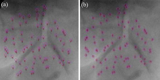

Fig. 6
Reconstruction results without (a) and with (b) automatic pose correction. The reconstructed seeds are projected back on the clinical image and are shown as purple circles. The segmented seed centroids are shown as red dots
Ultrasound-Fluoroscopy Registration
Registration of ultrasound and fluoroscopy (RUF) for image guidance in prostate brachytherapy has been extensively studied before. Todor et al. [35] put radio-opaque markers on the TRUS probe and used it for registration. Jain et al. [36] used mechanical registration of the FTRAC to the TRUS probe for this purpose and French et al. [37] used the images of the probe in the X-rays. For C-arm imaging the TRUS probe should be retracted, at least partially, to avoid occlusion of the seeds. This results in motion and deformation of the prostate in the posterior direction as the physicians usually press the probe against the prostate to achieve a good acoustic coupling. However, the marker- and fiducial-based registration methods rely on a relationship between the seed positions and the fiducials or marker that change by the retraction of the probe.
A seed-based registration method was used by Su et al. [38], Orio et al. [39], and Tutar et al. [40] in which manually selected seeds in ultrasound images were registered to seeds reconstructed from X-rays. Manual seed localization in ultrasound is difficult, time-consuming, subjective, and prone to errors. Moradi et al. [41] proposed a method for automatic yet partial seed segmentation in ultrasound using 3D template matching of radio-frequency signal. However, the detection rate in this method is low.
Fallavollita et al. [42] introduced an image-based ultrasound to fluoroscopy registration employing several filters such as phase congruency, noise reduction, and beam profiling to filter the ultrasound volume. They achieved successful registrations in a phantom study; however, their study on a single-patient data set showed only qualitative good results despite the complexity of the filters used.
We also use an image-based point-to-volume registration method that registers the reconstructed seeds from X-rays to an ultrasound volume of the prostate. Ultrasound and fluoroscopy are not generally compatible for intensity-based registration as fluoroscopy images have almost no soft tissue contrast. However, seed implantation inside prostate changes the ultrasound images, advantageously. Metallic seeds are hyper-echoic and result in bright regions in ultrasound images that correlate with the C-arm reconstructed seeds. We take advantage of this correlation for our registration purpose. However, the ultrasound volume should be processed such as described below in order to enhance the seed footprints and increase the robustness of the registration.
Ultrasound Image Processing
In the first step, a volume of interest (VOI) is selected. The VOI is selected as a cube that encloses the prostate and the seeds within. Image cropping can be done automatically, if the prostate contours are available. However, manual selection of the VOI is also fast and easy. As the seeds are hyper-echoic, they appear as outliers in VOI image intensity distribution (see Fig. 7a). Therefore, a threshold based on the image intensity statistics can be used to remove the background such that:

where μ u and σ u are the mean and standard deviation of image intensity in the VOI, respectively, and α is the threshold parameter. If α is too large, many of the true seeds will be removed and there will not be sufficient number of seeds for registration. On the other hand, if α is too small, the thresholded image contains many false positives that can produce local optimums for the registration. We chose α = 2.5 throughout this work for all of our phantom and clinical data sets. We have shown in [43] that our registration algorithm is robust to reasonable variations in α. In fact, we have shown that changing α ∈ {2,2.5,3} results only in submillimeter variations in the position of the registered seeds. The result of the thresholding step can be seen in Fig. 7b


(9)
Stay updated, free articles. Join our Telegram channel

Full access? Get Clinical Tree


