8 The Knee For MRI of the knee, the patient is positioned with the leg in comfortable external rotation. Sagittal, coronal, and axial imaging is obtained with fat-suppressed acquisition in at least one plane. To optimize spatial resolution, thinner segments are preferred, but the choice of segment thickness must be balanced with signal-to-noise and scan time constraints. In general, MRI systems with higher field strengths can achieve thinner segments with a better signal-to-noise ratio in less time than can units with lower field strength. For most SE protocols designed for knee imaging, the effective segment thickness is 3 to 4 mm; that for gradient-echo imaging is 1 to 3 mm. A typical low magnetic field strength protocol for knee imaging may include T1-weighted and T2-weighted sagittal acquisitions, a coronal STIR sequence, and an axial FSE T2-weighted sequence. A sagittal 3D gradient-echo sequence represents an additional option, particularly with low field strength systems; this high-resolution technique offers a relatively thin segment with a superior signal-to-noise ratio, useful for meniscal assessment. A high field strength approach to knee imaging may include the following sequences: • Sagittal FSE proton-density fat-suppressed sequence to evaluate the following: • Coronal FSE fat-suppressed T2-weighted sequence to assess the following: • Sagittal T1-weighted sequence to evaluate the following: • Axial FSE T2-weighted sequence primarily to assess the patellofemoral joint Acute knee trauma commonly presents with pain and hemarthrosis. ACL tears are seen in more than 70% of acute hemarthroses.1 Usually, ACL tears are associated with other injuries such as meniscal tears, osteochondral fractures, patellar dislocations, and ligament and tendon tears. MRI is commonly used to discern the etiology of an acute hemarthrosis, especially when the knee is too tender or the patient is too anxious for a thorough physical examination. MRI is especially helpful when conventional radiographs are negative. Typically, acute hemarthrosis appears as fluid within the joint with high signal intensity on T2-weighted images and intermediate signal intensity on T1-weighted images. Similar findings can be seen with inflammatory processes, resulting in a nontraumatic knee effusion, and the two processes may be differentiated by the clinician, based on the history and physical examination. The presence of blood in joint fluid causes a relatively brighter appearance on T1 imaging than that observed with nonhemorrhagic fluid because of the effect of methemoglobin. Hemosiderin deposition within joint fluid, associated with chronic hemorrhage or PVNS, appears dark on all pulse sequences.
 Specialized Pulse Sequences and Protocols
 Menisci
 Articular cartilage
 Cruciate ligaments
 Extensor mechanism
 Articular fluid
 Osseous injury
 Articular and meniscal cartilage
 Collateral supporting structures
 Fluid distribution
 Evaluate marrow and subcutaneous fat
 Detect heterotopic ossification
 Provide further evaluation of meniscal integrity
 Traumatic Pathology
Acute Hemarthrosis
Grade | Pathologic and MRI Findings |
1 | Degenerative process; focal, globular intrasubstance increased signal; no extension to articular surface |
2 | Degenerative process; horizontal, linear intrasubstance increased signal; no extension to articular surface |
3 | Meniscal tear; increased signal extends to or communicates with at least one articular surface |
4 | Complex tear/macerated meniscus |
Source: From Khanna AJ, Cosgarea AJ, Mont MA, et al. Magnetic resonance imaging of the knee: current techniques and spectrum of disease. J Bone Joint Surg Am 2001;83:128–141. Reprinted by permission.
Meniscal Tears
Meniscal tears are a very common finding on MRI. Clinical suspicion of a meniscal tear is a common reason for ordering an MRI. Tears can be a source of pain and disability, or they can be incidental findings. The tears can range from intrasubstance degeneration that can be seen only on MRI to complete tears that allow fragments of the meniscus to flip or displace.
Meniscal tears are graded according to how they appear on MRI (Table 8.12; Fig. 8.1), and are best seen on T1-weighted, gradient-echo, and proton-density images. The menisci are low intensity on all sequences.3–10 Most tears involve the medial meniscus, but most acute tears involve the lateral meniscus (Table 8.22,11). Special attention should be given to the menisci in the presence of a chronic ACL tear because associated meniscus tears are common. The medial meniscus is commonly torn in the chronically ACL-deficient knee because the meniscus plays a secondary stabilizing role to anterior tibial translation.
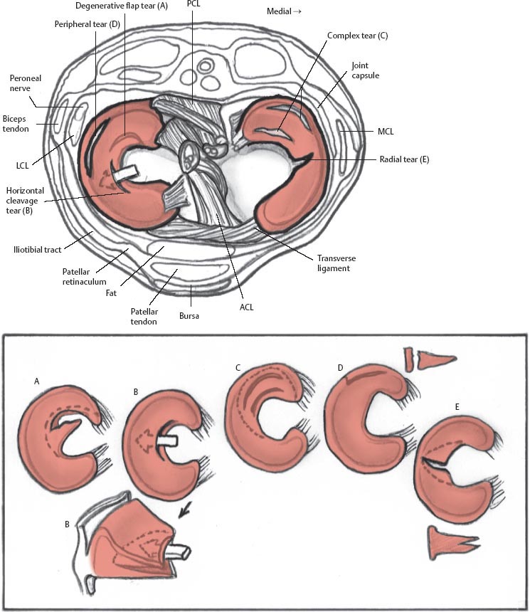
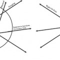
Fig. 8.1 Artist’s sketch illustrating the morphology of meniscal tear patterns and relevant anatomy of the knee: (A) degenerative flap tear, (B) horizontal cleavage tear, (C) complex tear, (D) peripheral vertical longitudinal tear, and (E) vertical radial tear.
Meniscal Tear Morphology | Description | Appearance on MRI |
Horizontal | Separates meniscus into superior (femoral) and inferior (tibial) fragments | Primarily horizontal signal on sagittal images |
Vertical radial | Splits central margin of meniscus | Vertical signal oriented perpendicular to the curvature of the meniscus |
Vertical longitudinal | Extends along length of meniscus; separates meniscus into inner and outer fragments | Vertical signal oriented parallel to the curvature of the meniscus. |
Bucket handle | Subtype of the longitudinal tear in which the displaced central fragment resembles a bucket handle | “Double-PCL” sign; displaced fragment often seen parallel to the PCL in the intercondylar notch on sagittal images |
Complex | Combination of multiple planes; commonly horizontal and radial | Characteristics of each tear type or fragmented/macerated |
Meniscocapsular separation | Rupture of meniscus-capsule junction | Increased signal between the edge of the meniscus and the capsule |
Source: Adapted from Khanna AJ, Cosgarea AJ, Mont MA, et al. Magnetic resonance imaging of the knee: current techniques and spectrum of disease. J Bone Joint Surg Am 2001;83:128–141, combined with information from Kelley EA, Berquist TH. Knee. In: Berquist TH, ed. MRI of the Musculoskeletal System. Philadelphia: Lippincott Williams & Wilkins; 2006:303–429. Adapted by permission.
The types of meniscal tear morphologies have been well described (Table 8.22,11). In early publications on MRI evaluation of meniscal pathology, detection focused primarily on meniscal signal intensity patterns and their relationship to the meniscal surface.12,13 Grade I and grade II9 meniscal tears referred to increased intrameniscal signal that appeared punctate or linear, respectively, and were particularly evident on T1-weighted images. The grade III designation indicated that the signal intensity pattern communicated with the superior or inferior meniscal surface, and therefore most likely corresponded to an arthroscopically identifiable meniscal tear.9 If grade II meniscal pathology was reported in an MRI interpretation as a grade II tear, however, it could create the erroneous impression that meniscal surface pathology existed. Although grade II intrameniscal signal can reflect the presence of a meniscal contusion or an intrameniscal tear, it may also denote myxoid internal meniscal degeneration, artifact (magic angle effect or truncation), or normal meniscal vascularity in a child or young adult.14,15 This grading system also does not consider morphologic alterations in characterizing meniscal pathology. Because the morphology of a meniscal tear impacts its relative clinical significance and influences surgical planning, a more specific classification system, currently afforded wide acceptance, uses MRI findings to categorize tears as follows13:
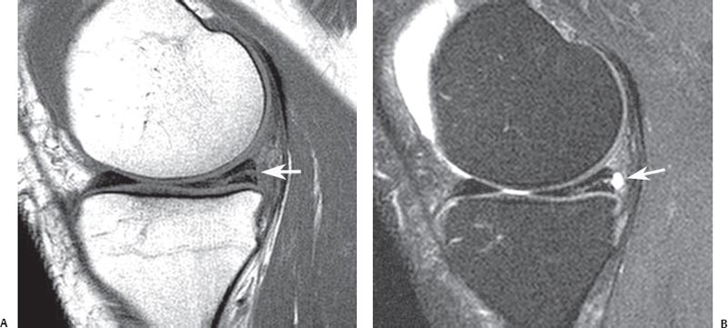
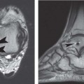
Fig. 8.2 Horizontal tear in the posterior horn of the medial meniscus. Sagittal T1-weighted (A) and fat-suppressed proton-density (B) images showing a horizontal tear (arrow on each) communicating with the undersurface of the meniscus. Note the small meniscal cyst posterior to the meniscus on the fat-suppressed proton-density image.
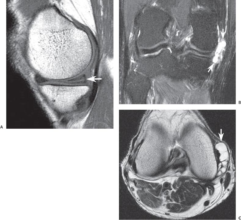
Fig. 8.3 Horizontal medial meniscal tear with large meniscal cyst in the right knee. (A) A sagittal T1-weighted image shows a horizontal tear (arrow) of the posterior horn of the medial meniscus. (B) A coronal fat-suppressed T2-weighted image shows a large meniscal cyst (arrows) extending medial to the medial compartment. (C) An axial T2-weighted image shows a multiloculated meniscal cyst (arrow).
• Horizontal
• Vertical radial
• Vertical longitudinal with/without flap displacement
• Complex
Horizontal tears divide the meniscus into superior and inferior components, identified on sagittal and coronal imaging series (Fig. 8.2). The tear often communicates with the inferior meniscal surface; sometimes a concomitant meniscal cyst is identified, involving the perimeniscal soft tissue (Fig. 8.3).
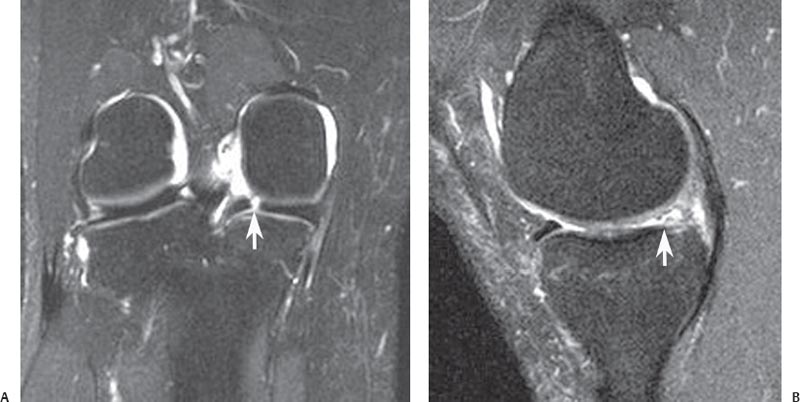
Fig. 8.4 Vertical radial meniscal tear in the posterior horn of the medial meniscus in the right knee. (A) A coronal fat-suppressed T2-weighted image shows a vertical defect (arrow) involving the posterior horn of the medial meniscus. (B) A sagittal fat-suppressed proton-density image, obtained in the plane of the tear, shows truncation (arrow) and abnormal signal intensity involving the posterior horn. Note the normal anterior horn.
Vertical radial tears exhibit a linear signal pattern. They violate the superior and inferior meniscal surfaces and are oriented perpendicular to the meniscal axis of curvature.16 As such, if a vertical radial tear involves the anterior or posterior portion of the meniscus, the tear will show a linear vertical configuration on coronal images (Fig. 8.4A) and an abrupt truncation of the central meniscal contour on sagittal images (Fig. 8.4B). With this type of tear, the change in meniscal morphology, appreciated in the imaging plane oriented parallel to the tear, is equally as important as the surface communication of linear abnormal meniscal signal intensity, noted in the imaging plane perpendicular to the axis of the tear. If the vertical radial tear involves the mid-body of the meniscus, a linear meniscal defect is noted on sagittal images (Fig. 8.5A), and blunting or truncation of the central meniscal contour is observed on coronal images (Fig. 8.5B). A commonly overlooked vertical radial tear occurs at the root of the posterior horn of the medial meniscus (Fig. 8.6). This tear, particularly common in obese patients, destabilizes the meniscus, and medial extrusion of the meniscus is often identified on MRI. Chondromalacia and osseous stress injury are also frequently observed in association with these radial tears of the root of the posterior horn of the medial meniscus.17
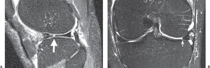
Fig. 8.5 Vertical radial meniscal tear in the mid-body lateral meniscus in the left knee. (A) A sagittal fat-suppressed proton-density image shows a vertical tear (arrow) of the central edge of the lateral meniscus, oriented perpendicular to the curvature of the meniscus. Note the superimposed horizontal tear of the anterior horn. (B) A coronal fat-suppressed T2-weighted image shows the same tear with truncation of the central meniscal margin (arrow).
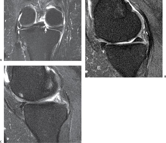
Fig. 8.6 Vertical radial tear of the meniscal root in the right knee. (A) A coronal fat-suppressed T2-weighted image shows a vertical radial defect (arrow) at the meniscal root. (B) A sagittal fat-suppressed proton-density image, obtained just medial to the tear, shows normal posterior horn morphology. (C) A sagittal fat-suppressed proton-density image, obtained in the plane of the tear, shows abrupt transition to markedly abnormal posterior meniscal morphology, corresponding to the meniscal root tear.
Vertical longitudinal tears also exhibit a vertical signal orientation on MRI, but because the tear is oriented parallel to the axis of meniscal curvature, it is identified as a vertical linear signal intensity interfacing with the superior and inferior meniscal articular surfaces on sagittal and coronal imaging planes. Peripheral vertical longitudinal tears of the posterior horn of the medial meniscus and vertical longitudinal tears of the posterior horn of the lateral meniscus at the attachment of the meniscofemoral ligament are commonly associated with ACL tears (Fig. 8.7). Displacement of a meniscal flap associated with a vertical longitudinal tear may occur, and unstable meniscal tears are more likely to be symptomatic and impair biomechanics; in such circumstances, surgical intervention usually is necessary to restore function.18 Failure to address surgically the presence of a displaced meniscal flap or fragment represents a cause of persistent joint pain and dysfunction after arthroscopy.19 Unstable meniscal tears may exhibit central or peripheral flap displacement. A typical bucket-handle tear represents a vertical longitudinal tear with central displacement of meniscal tissue. If the medial meniscus is involved, the flap is displaced inferior to the PCL, creating the double-PCL sign20 (Figs. 8.8 and 8.9). Bucket-handle tears of the lateral meniscus often exhibit anterior central displacement of a flap arising from the posterior horn of the meniscus (Fig. 8.10). Displaced bucket-handle tears are a common cause of locked knee in an athlete. Posterior central flap displacement may also occur with a flap arising from the posterior horn of the medial meniscus and the displaced meniscal tissue positioned in the recess between the distal PCL and the medial meniscus (Fig. 8.11). Meniscal tissue may also displace peripherally into the recess between the capsule and the femoral condyle (Fig. 8.12) or between the capsule and the tibial plateau (Fig. 8.13). Although peripherally displaced tears are less likely than centrally displaced tears to result in locking, they tend to cause adjacent capsular inflammation and osseous stress reaction, contributing to pain related to the meniscal tear. Preoperative identi fication and localization of the displaced meniscal flap with MRI contribute to a more expeditious operative procedure.10
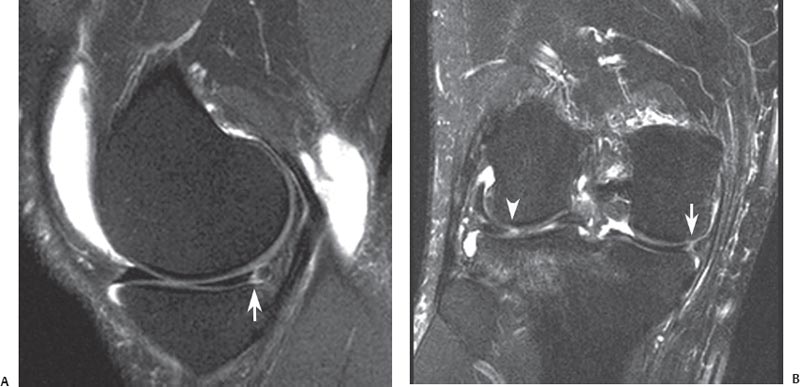
Fig. 8.7 Vertical longitudinal tear in the right knee. (A) A sagittal fat-suppressed proton-density image shows a peripheral vertical longitudinal tear (arrow) of the posterior horn of the medial meniscus. Note the effusion and Baker cyst. (B) A coronal fat-suppressed T2-weighted image shows the vertical longitudinal tear (arrow), propagating parallel to the meniscal curvature. Note the tear of the posterior horn of the lateral meniscus (arrowhead) with an adjacent lateral tibial plateau bone bruise in this patient with an acute ACL tear.
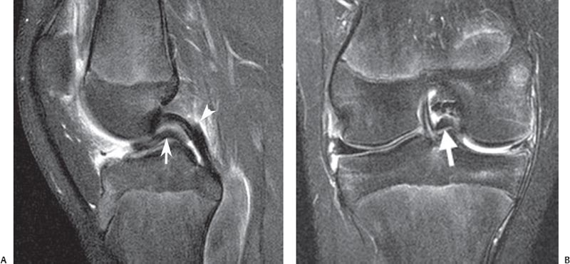
Fig. 8.8 Bucket-handle tear in the right knee. (A) A sagittal fat-suppressed proton-density image shows a meniscal flap (arrow), arising from the medial meniscus and displaced inferior to the PCL (arrowhead), exhibiting the double-PCL sign. (B) A coronal fat-suppressed T2-weighted image shows a centrally displaced meniscal flap (arrow) inferior to the PCL. Note the abnormal morphology of the nondis-placed medial meniscal remnant.
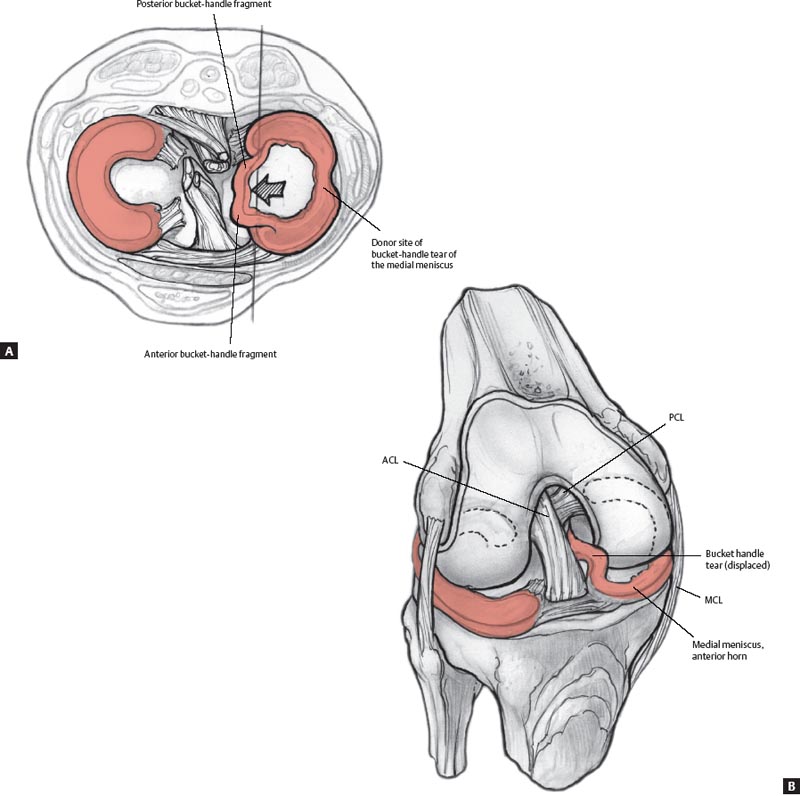
Fig. 8.9 Artist’s sketches illustrating a displaced bucket-handle tear of the medial meniscus in the axial plane (A) and from an anterior perspective (B).
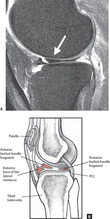
Fig. 8.10 A sagittal fat-saturated proton-density image (A) and artist’s drawing (B) showing anterior displacement of the posterior horn of the lateral meniscus (arrow) with the displaced flap positioned just posterior to the anterior horn of the lateral meniscus.
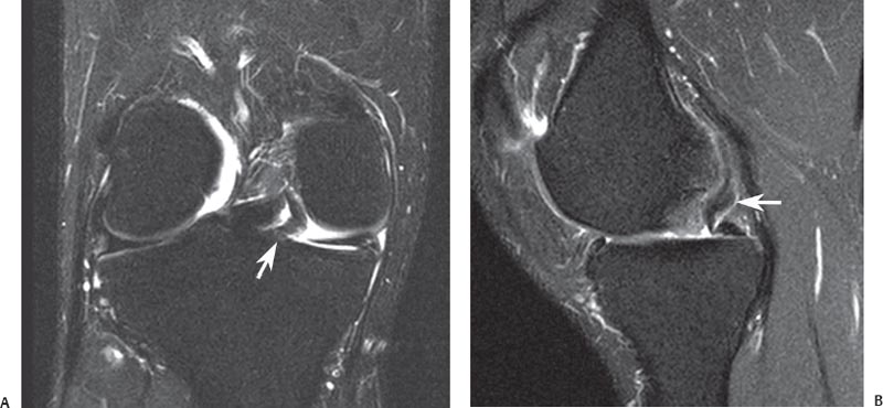
Fig. 8.11 Displaced meniscal tear in the right knee. Coronal fat-suppressed T2-weighted (A) and sagittal fat-suppressed proton-density (B) images show the posterior central displacement of a medial meniscal flap (arrow on each).
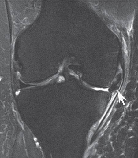
Fig. 8.12 This coronal fat-suppressed T2-weighted image of the right knee shows the peripheral superior displacement of a large meniscal flap (arrow), arising from the medial meniscus and extending into the recess medial to the medial femoral condyle.
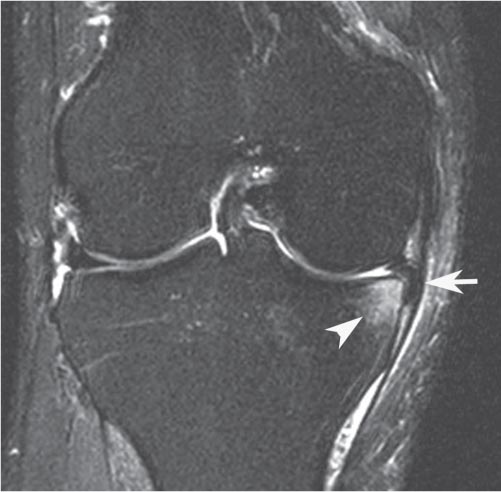
Fig. 8.13 This coronal fat-suppressed T2-weighted image of the right knee shows the peripheral inferior displacement of a meniscal flap (arrow), arising from the medial meniscus and extending into the recess medial to the medial tibial plateau. Note the adjacent osseous stress reaction (arrowhead) and pericapsular edema.
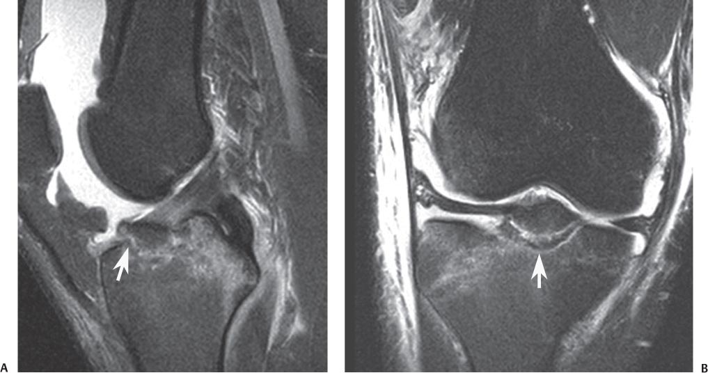
Fig. 8.14 ACL avulsion. Sagittal fat-suppressed proton-density (A) and coronal fat-suppressed T2-weighted (B) images of the right knee show an avulsion (arrow on each) of the tibial attachment of the ACL.
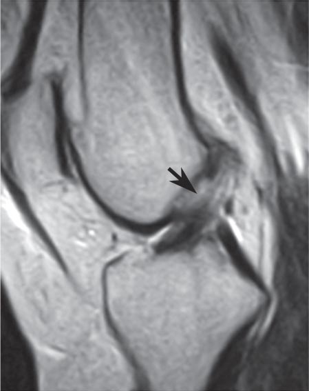
Fig. 8.15 This sagittal T2-weighted image shows a proximal ACL tear (arrow).
ACL Tears
ACL evaluation is one of the primary indications for MRI of the knee.21 The patient usually describes a noncontact, twisting or valgus injury to the knee with a planted foot and often describes sensing a “pop” inside the knee. The patient may experience a subsequent lack of quadriceps function because of the resulting effusion. Physical examination findings include a positive Lachman test and pivot shift. The patient’s anxiety may make the physical examination equivocal, increasing the importance of the MRI.
The adult ACL usually avulses from its femoral attachment or develops an intrasubstance tear. The tendon does not have to dissociate completely to become incompetent.22 The presence of blood at the femoral avulsion can appear as a “pseudomass” because of volume averaging.23 With skeletally immature patients, the ACL may remain intact and avulse a fragment of bone off of the tibial attachment (Fig. 8.14). Treatment is determined by the degree of displacement, but it usually requires surgical fixation via arthroscopic or open techniques.
The signs of an ACL injury on MRI include abnormal ligament signal and loss of the normal orientation and continuity of the ligament (Fig. 8.15). There are primary and secondary signs of ACL tears as visualized on MRI (summarized in Table 8.324–26). MRI findings commonly associated with acute ACL injury include loss of ligament continuity and replacement of the ligament by a poorly marginated pseudomass that shows high signal on T2-weighted imaging and low signal on T1-weighted imaging (Fig. 8.16). With both acute and chronic ACL tears, the ligament may appear abnormal in angulation, typically because of inferior displacement of the proximal portion of the ligament. Acute tears of the ACL are often accompanied by bone bruises involving the posterior aspect of the lateral tibial plateau, the anterolateral aspect of the lateral femoral condyle with impaction of the articular surface notch, and the posterior aspect of the medial tibial plateau (Fig. 8.17). The osseous contusions are related to the initial pivot shift rotational stress (lateral injuries) and the subsequent abrupt return to normal alignment (medial plateau injury). Additional findings include anterior translation of the tibia, resulting in increased PCL flexion, popliteus muscle strain, peripheral tears of the posterior horn of the medial meniscus (Fig. 8.18), and tears of the lateral meniscus associated with the attachment of the meniscofemoral ligament (Fig. 8.19).
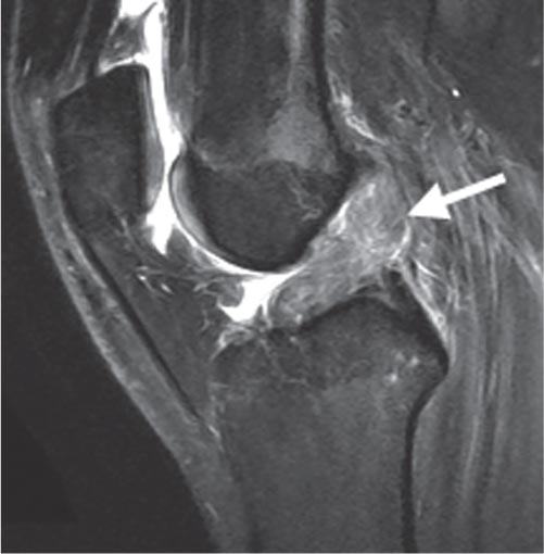
Fig. 8.16 This sagittal fat-suppressed proton-density image shows the pseudomass appearance (arrow) of an acute ACL tear.
Primary signs |
• Nonvisualization of ligament • Complete disruption of a ligament segment • Abnormal signal within ligament on T2-weighted images • Alteration of normal linear configuration of ligament • Alteration of normal angulation of ligament |
Secondary signs |
• Bone contusion (posterolateral and posteromedial tibia, lateral condyle of femur) • Deepening of lateral femoral condyle notch or sulcus • Anterior translation of tibia >5 mm from posterior margin of femoral condyle • Buckling of the PCL (decreased angle of the PCL) • Segond fracture • Meniscal tear • Posterior horn medial meniscus and tear of the lateral meniscus at the meniscofemoral ligament attachment • Posterior displacement of posterior horn of lateral meniscus |
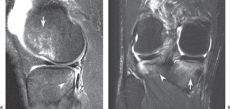
Fig. 8.17 Bone bruise pattern with ACL tear. (A) A sagittal fat-suppressed proton-density image shows a bone bruise (arrow) with osteochondral impaction involving the lateral femoral condyle and a bone bruise (arrowhead) involving the posterior aspect of the lateral tibial plateau. (B) A coronal fat-suppressed T2-weighted image of the right knee shows bone bruises involving the posterior aspect of the lateral tibial plateau (arrowhead) and medial tibial plateau (arrow).
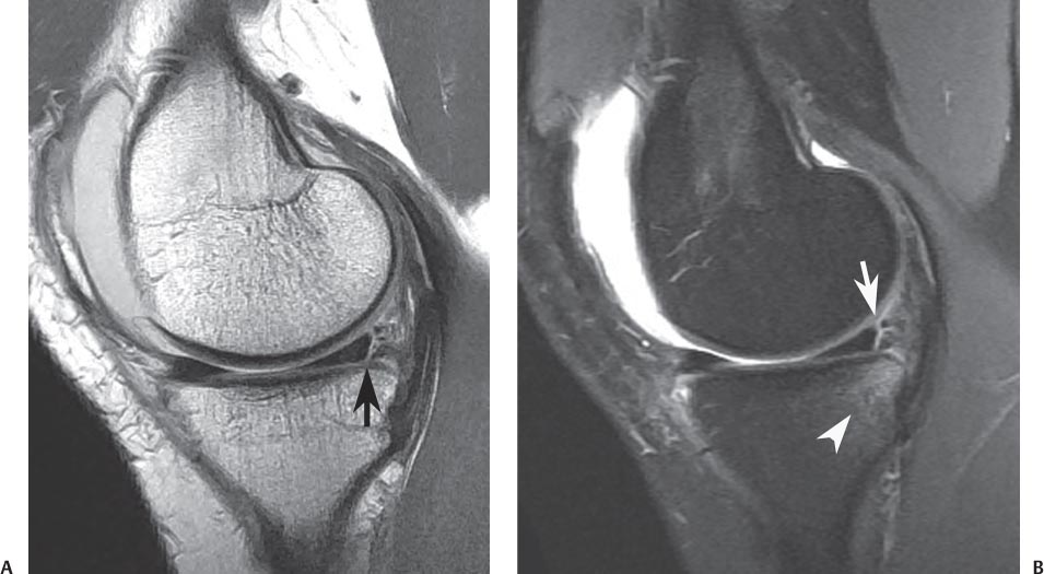
Fig. 8.18 Medial meniscal tear with ACL tear. Sagittal proton-density (A) and sagittal fat-suppressed T2-weighted (B) images show a peripheral tear (arrow on each) of the posterior horn of the medial meniscus. Note the bone bruise (arrowhead on B) of the posterior aspect of the medial tibial plateau.
Other knee structures are also commonly injured at the time of ACL injury, and it is imperative that the MRI be evaluated for these concomitant injuries. These injuries, such as meniscus tears, bone bruises, and cartilage injuries, not only may need to be addressed surgically, but also aid in the diagnosis when the ACL tear is not obvious.27
A variety of other radiographic findings seen in association with ACL tears are considered secondary signs (Table 8.324–26). A relatively small avulsion fracture seen at the lateral tibial cortex (known as a Segond fracture) is caused by avulsion of the middle third of the lateral capsule28 (Fig. 8.20).
When the ACL tears, the posterior tibial plateau translates anteriorly, impacting the anterior aspect of the lateral femoral condyle in the region of the terminal sulcus. The resulting contusion leaves a bone bruise pattern in these two locations, best seen on T2-weighted images (Fig. 8.17). This pathologic contact of the tibial and the femoral condyles may leave an indentation or notch, also called a “deepened terminal sulcus,” particularly when the patient experiences repeated instability episodes. Another sign of chronic ACL insufficiency is buckling of the PCL, which suggests that the tibia is positioned in an anteriorly displaced position. Patients with chronic ACL insufficiency also frequently develop secondary degenerative changes, including partial- and full-thickness chondral lesions, peripheral osteophytes, and peaking of the tibial spines.
When evaluating the MRI study of a patient with ACL injury, multiple factors should be taken into consideration and included in the description of the MRI findings, including the location and degree of disruption of the ACL. In addition, the collateral ligaments, PCL, and secondary restraints (including the menisci) should be carefully reviewed. It is also important to review the status of the osseous structures and articular cartilage because injuries to these structures can also be treated at the time of ACL reconstruction and repair. Lastly, the condition of any tissues that might be used when reconstructing the ACL should be evaluated, and injury to them should be ruled out.
Chronic degeneration of the ACL should be differentiated from an acute ACL injury or tear. Patients with chronic degeneration often present with chronic knee discomfort and a vague, nonspecific knee pain. The process is thought to be secondary to repetitive low-energy microtrauma as opposed to a single high-energy event that might produce an acute ACL tear. Minimal to no instability is seen on physical examination. The MRI may show evidence of advanced degeneration of the ACL with thickening of the ligament and less increase in T2-weighted signal than that which is typically seen with an acute tear (Fig. 8.21). Such patients also often have similar PCL involvement.
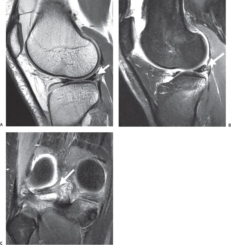
Fig. 8.19 Lateral meniscal tear with ACL tear. Sagittal proton-density (A), sagittal fat-suppressed T2-weighted (B), and coronal fat-suppressed T2-weighted (C) images of the right knee show a peripheral tear of the posterior horn of the lateral meniscus (arrow on each), associated with the attachment of the meniscofemoral ligament. Note the proximal tibial bone bruises, typical for an acute ACL injury.
PCL Tears
The PCL is more robust and more consistently has lower signal on MRI than does the ACL. MRI is very sensitive for tears of the PCL because of its normal low signal (Fig. 8.22). Any increased signal within the PCL on T2-weighted images is suspicious for injury.29–31 The PCL can be torn partially, indicated by increased signal on T2 images with the ligament in continuity (Fig. 8.23), or completely, visualized as a loss of continuity of the ligament. Bone bruises may be present, depending on the mechanism of injury. A blow to the proximal tibia from a dashboard during a motor vehicle accident can produce soft-tissue edema and a bone contusion involving the tibial plateau, best seen on T2-weighted images. Bone bruises may be present on the anterior tibial plateaus and the femoral condyles if the PCL injury occurs from a hyperextension mechanism.

Fig. 8.20
Related posts:
Stay updated, free articles. Join our Telegram channel

Full access? Get Clinical Tree


