11 The Lumbar and Thoracic Spine Although imaging protocols of the lumbar spine for specific indications can vary among institutions, standard MRI studies of the lumbar spine for degenerative pathologies usually include the following sequences: • Sagittal T1-weighted SE • Sagittal T2-weighted FSE • Sagittal T2-weighted with fat suppression or sagittal STIR • Axial T2-weighted FSE • Axial T1-weighted SE or axial gradient echo T1-weighted images are good for identifying anatomy and assessing the quantity of fat in neural foramina and the epidural spaces. They also help identify the presence of fracture lines. However, edema has low signal on T1-weighted images and may be difficult to identify. Signal on T1-weighted images increases in the presence of gadolinium contrast, so these images are used to assess for contrast enhancement. Contrast enhancement is particularly useful in differentiating recurrent disc pathology from scar tissue and in assessing infection, neoplasms, and vascular malformations. Contrast enhancement may be made more conspicuous by obtaining postcontrast fat-suppressed images. T2-weighted images are sensitive to edema, which is usually one of the early signs of pathology. Distinction between fat and fluid (edema) may be difficult on T2-weighted images. For this reason, fat suppression via a fat-suppressed T2-weighted or STIR image may be obtained to make edema more conspicuous. STIR images are preferred over fat-suppressed T2-weighted images for patients with spinal instrumentation because STIR images are less prone to magnetic susceptibility artifacts. T2-weighted and fat-suppressed T2-weighted or STIR images are extremely helpful in identifying ligamentous injury, subtle fractures, neoplasms, infection, and fluid collections, including joint effusions. Highly T2-weighted images produce an “MR myelogram” that provides a nice perspective, which is similar to that of images obtained with conventional myelography and CT myelography. As with other myelographic images, these MR images can be used to evaluate for spinal stenosis. However, such images should always be interpreted in conjunction with other MR pulse sequences because they may be prone to artifacts that exaggerate or underestimate abnormalities, including the degree of stenosis. By decreasing the degree to which protons are “flipped” during image acquisition (compared with T1-weighted and T2-weighted images in which they are flipped by 90 to 180 degrees), gradient-echo images can be acquired much more quickly. Adjustments in the “flip angle,” TR, and TE can create T1 and T2 weighting in these images. Gradient-echo images are very susceptible to magnetic susceptibility artifacts, which make them quite useful for the detection of small areas of hemorrhage, such as those that occur with trauma and vascular malformations. On the other hand, this susceptibility also causes gradient-echo images to overestimate canal and foraminal stenosis because of artifact from the adjacent bone. Advances in MRI techniques are decreasing the latter problem.1 Because of the rapidity with which images are acquired, they can be obtained with higher resolution and even as a 3D volume, which allows for isotropic voxels and reformations in multiple planes. Patients with suspected lumbar spine injuries should be evaluated initially with conventional radiographs. CT imaging offers greater osseous detail than do conventional radiographs and may reveal fractures or details that are not detected with radiography. MRI provides superior visualization of soft tissues compared with conventional radiographs or CT images and is useful for the assessment of ligamentous injury, degree of spinal stenosis, additional fracture evaluation, and associated findings such as epidural hematomas. Occult fractures not visible on conventional radiographs or CT images may be detected by the presence of vertebral body edema on MR images. Although MRI is extremely sensitive in identifying thoracolumbar spine fractures, their characteristics and the exact appearance of the osseous components can be challenging; CT may be a better choice for assessing these aspects of the fractures. MRI is indicated when neurologic deficit, vascular injury, or soft-tissue injury is suspected in the setting of trauma. It is also useful for the assessment of posttraumatic sequelae.
 Specialized Pulse Sequences and Imaging Protocols
 Traumatic Conditions
Anatomy | Evaluation |
Spinal column/vertebral bodies | Alignment, vertebral body fracture, posterior element fracture, edema, degenerative change |
Ligaments | Anterior longitudinal ligament, posterior longitudinal ligament, interspinous ligament, edema/rupture |
Spinal cord | Edema, hemorrhage, compression, syrinx |
Epidural space | Hematoma, disc herniation, osseous fragment |
Source: Takhtani D, Melhelm ER. MR imaging in cervical spine trauma. Magn Reson Imaging Clin N Am 2001;8:615–634. Modified with permission.
A systematic approach (see Chapter 3) for the evaluation of lumbar spine MRI should be used to avoid missing pathologic conditions (see Table 11.1 for important lumbar spine structures to evaluate). In addition, it is essential that the interpretation of the MRI findings be performed in conjunction with that of other available imaging modalities, including conventional radiographs (with flexion and extension views if clinically indicated) and CT (see Chapter 17).
Classification of Thoracolumbar Spine Trauma
Thoracolumbar spine trauma is a common and complex condition. There are many classification systems, all of which are based on a variety factors such as mechanism of injury, morphology of fracture, involvement of columns, and presence, absence, or degree of neural compromise.2–4 As with many classification systems, those for the evaluation of thoracolumbar spine trauma have not been universally accepted. This lack of acceptance may be the result of their complexity, lack of reproducibility, or poor validity, or any combination thereof.
Recently, the Thoracolumbar Injury Classification and Severity Score has recognized the importance of the following three factors5:
• Fracture morphology (Fig. 11.1)
• Integrity of the posterior ligamentous complex (stability or potential for neurologic compromise)
• Neurologic status of the patient5
Although a detailed review of this classification system is outside the scope of this chapter, these three components are used here to review and highlight the role of MRI in the evaluation of patients with thoracolumbar spine trauma. In addition, a systematic evaluation of these three components and calculation of an injury severity score5 can be used to guide the treatment of patients with thoracolumbar spine fractures.
Role of MRI in Thoracolumbar Spine Trauma
Evaluation of Fracture Morphology
The first element in the MRI evaluation of a thoracolumbar injury is the assessment of fracture morphology. The morphology description includes the type of fracture (compression, burst, etc.) and the position of various osseous fragments relative to their anatomic origin and to the spinal canal. As discussed above, for the assessment of the osseous components of a fracture, CT is superior to conventional radiography and MRI because of the excellent spatial resolution and osseous detail it provides (Fig. 11.2). MRI may help provide additional information regarding the morphology of a fracture in a limited number of situations.
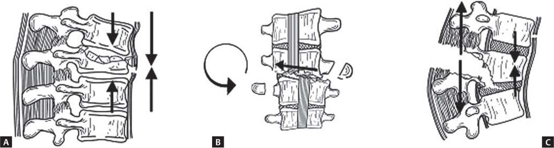
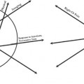
Fig. 11.1 Artist’s sketches of the three major morphologic descriptors in the Thoracolumbar Injury Classification and Severity Score (compression, translation/rotation, and distraction). These descriptors are determined from a combination of conventional radiographs, CT images, and MRI sequences. (A) In compression, the vertebral body buckles under load to produce a compression or burst fracture. (B) In translation/rotation, the vertebral column is subjected to shear or torsional forces that cause the rostral part of the spinal column to translate or rotate with respect to the caudal part. (C) In distraction, the rostral spinal column becomes separated from the caudal segment because of distractive forces. Combinations of these morphologic patterns may occur. (From Vaccaro AR, Lehman RA Jr, Hurlbert RJ, et al. A new classification of thoracolumbar injuries. The importance of injury morphology, the integrity of the posterior ligamentous complex, and neurologic status. Spine 2005;30:2325–2333. Reprinted with permission.)
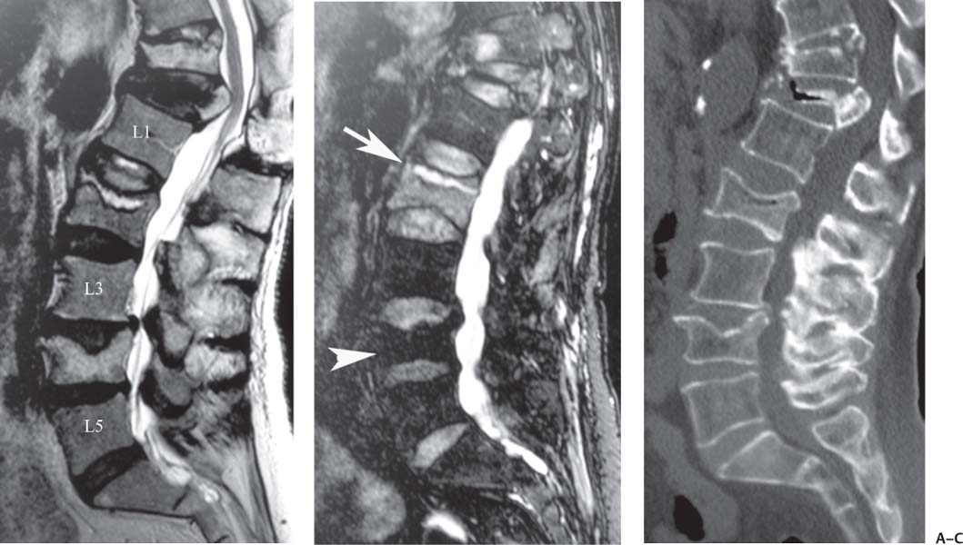
Fig. 11.2 Osteoporotic vertebral fractures. (A) A sagittal T2-weighted image showing multiple vertebral fractures, including vertebral compression fractures at L4, L2, and T11, and a burst fracture at T12. Note the bright T2-weighted signal fracture line at L2, characteristic of a benign osteoporotic fracture. (B) A sagittal STIR image shows a linear region of increased signal intensity compatible with edema in the L2 vertebral body (arrow), which is compatible with an acute fracture. Note the diffuse edema in the vertebral body that could be mistaken for diffuse bone marrow involvement by a neoplastic process. There is no increase in signal intensity in the L4 vertebral body (arrowhead), which is compatible with a chronic fracture. (C) A sagittal reconstructed CT image shows the osseous details of the fractures. The osseous margins are clearly defined, and the retropulsed posterior fragment characteristic of a benign osteoporotic fracture is evident at T12.
For example, subtle fractures may be difficult to identify on CT or conventional radiographs, especially in patients with degenerative disc disease where end-plate anatomy and vertebral morphology are affected by the degenerative changes. Furthermore, osteoporotic and osteopenic patients may show less osseous reactive change, which typically allows for the detection of subtle or subacute fractures on conventional radiographs. Fluid-sensitive pulse sequences such as fat-suppressed T2-weighted or STIR images are excellent for identifying areas of subtle bone marrow edema and focusing attention on an area of potential osseous injury. This bone marrow edema often appears almost immediately after injury and can persist for several months or even a year thereafter.6,7 It should be noted, however, that the differential considerations for bone marrow edema in a vertebral body are varied and include other entities such as tumors, end-plate degeneration, and infection. For this reason, correlation with other imaging findings, imaging techniques, and clinical information is important for making a definitive diagnosis.
For patients in whom vertebral compression fractures are associated with pain, vertebral augmentation procedures such as vertebroplasty or kyphoplasty may be considered as a treatment option. In a study of patients with chronic (1 year) vertebral compression fractures treated with vertebroplasty, Brown et al.7 found that clinical improvement was definitively correlated with the presence of preprocedural bone marrow edema. Thus, it is essential that the MR images be reviewed for the absence, presence, and degree of bone marrow edema for each fracture (Fig. 11.2).
Differentiating posttraumatic and osteoporotic fractures from neoplastic or pathologic fractures can be challenging (Figs. 11.2 and 11.3), especially in elderly patients. Neoplastic processes tend to fracture when most of the vertebral body is infiltrated with tumor (Fig. 11.3). Key MRI features that suggest the presence of a malignant fracture include the following8:
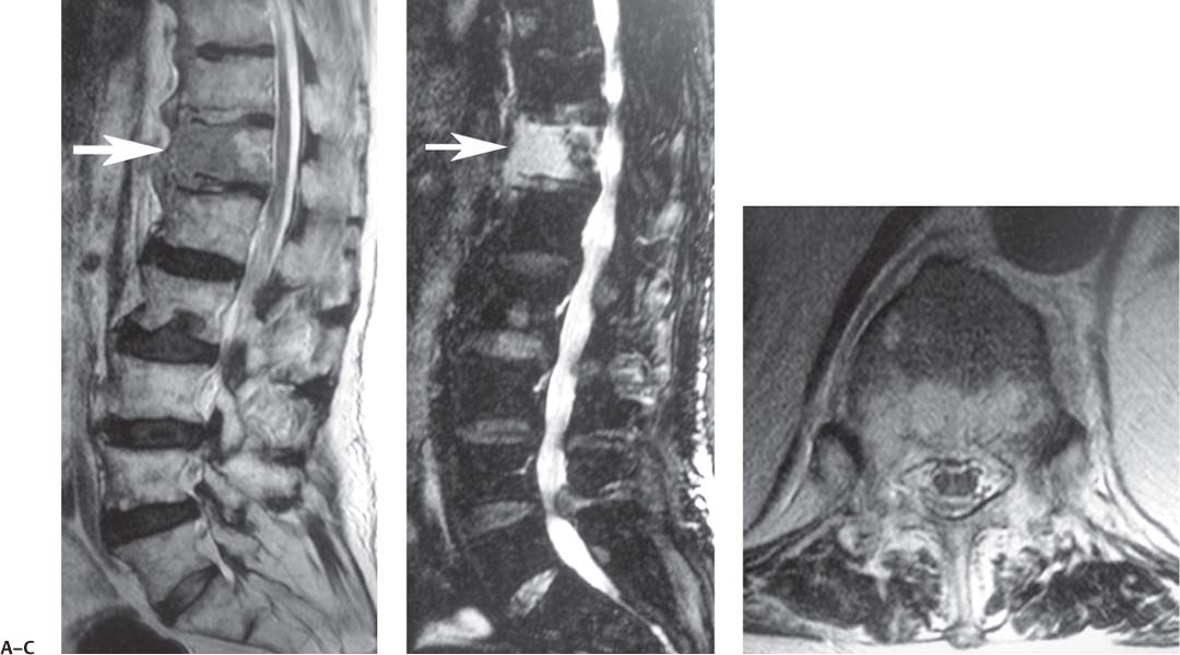
Fig. 11.3 Vertebral body metastasis in a patient with lung cancer. (A) A sagittal T2-weighted image showing heterogeneous bone marrow signal intensity in multiple vertebral bodies (which can be seen with osteoporosis) but most prominently within the anterior half of the T12 vertebral body (arrow). Note that the anterior aspect of the vertebral body appears expanded as it is infiltrated with tumor. (B) A sagittal STIR image shows intensely increased signal intensity in the same region (arrow). (C) An axial T2-weighted image shows heterogeneous signal intensity within the vertebral body. A percutaneous biopsy confirmed evidence of metastatic lung cancer.
• Convex posterior margin of the vertebral body (from tumor infiltration) (Fig. 11.4)
• Abnormal signal in the posterior elements
• Epidural mass and neural encasement by the same focal paraspinal mass
• Presence of other osseous lesions
In the search for other lesions, care should be taken not to mistake additional osteoporotic vertebral fractures for metastatic lesions. A horizontal linear bright fracture line on T2-weighted images is considered the most reliable sign of a nonmalignant fracture (Fig. 11.2). Other signs that decrease the likelihood of underlying tumor include a retropulsed fragment off of the posterior aspect of the vertebral body, multiple fractures, and normal bone marrow signal.8,9 Because contrast enhancement is often seen with acute benign fractures, it is no longer considered diagnostic for an underlying lesion or malignancy.8,10
Assessment of Stability
The term spinal stability refers to the ability of the spine to limit neurologic compromise under physiologic loads. Panjabi et al.11 have defined spinal stability as the degree of motion that prevents pain, neurologic deficit, and abnormal angulation. The definition can also be extended to include the ability of the spine to avoid the development of spinal deformity. Two key concepts in the MRI determination of spinal stability are the three-column concept and the assessment of the posterior ligamentous complex.
Three-Column Concept
More than 25 years ago, Denis4 introduced the concept of the three-column spine and its clinical significance in the evaluation of spinal stability in patients with acute thoracolumbar injuries. Although the reliability and validity of the Denis system have been questioned,12 it is still used frequently to help evaluate the degree of spinal instability. Spinal instability may be assessed based on the number of columns involved in an injury. The three columns are defined as follows:
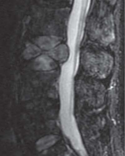
Fig. 11.4 A sagittal STIR image showing a pathologic burst fracture of the L3 vertebral body in a patient with metastatic lung cancer. Note the diffusely increased signal within the vertebral body and the convex posterior margin of the vertebral body.
• Anterior: anterior longitudinal ligament and the anterior portion of the vertebral body and annulus
• Middle: posterior vertebral body and annulus, and the posterior longitudinal ligament
• Posterior: facet joints, posterior elements, and posterior ligaments (supraspinous and interspinous ligaments and ligamentum flavum)
If one column is involved, the spine is generally considered stable; with two-column involvement, the spine is variably stable, depending on the degree of involvement; and the involvement of all three columns leads to a highly unstable spine.
Posterior Ligamentous Complex
The posterior column and posterior ligamentous complex is an area of increasing concern in spinal stability (Fig. 11.1C).5,13,14 The components of the posterior ligamentous complex include the supraspinous ligament, inter-spinous ligament, ligamentum flavum, and the facet joint capsules.5 The three ligaments that comprise the posterior ligamentous complex normally appear as dark and continuous bands on T1-weighted and T2-weighted images. When traumatized, they may show increased signal on fluid-sensitive pulse sequences (T2-weighted fat-suppressed and STIR) (Fig. 11.5) or associated hematomas. Discontinuity of the dark signal of the fibers is also seen on MRI. It has been suggested that the MR images be reviewed with the intent of describing these ligaments to be intact, indeterminate, or disrupted.5
Subtle fractures and dislocations of the facet joints and posterior elements are detected well on CT, but in some instances the edema identified on MRI may be helpful in combination with close scrutiny of the CT images to identify subtle fractures. However, the true role of MRI in these instances is in identifying ligamentous injuries and hematomas; 28% to 47% of patients with thoracolumbar burst fractures are estimated to have disruption of the posterior ligamentous complex.15
Assessment of Neural Compromise
MRI plays its most vital role in the assessment of neural compromise and is excellent in its ability to determine the cause of compression. Neural compromise can be graded on MRI as mild, moderate, or severe (see Lumbar Spinal Stenosis, below). In addition to an evaluation of the degree of stenosis, the type of stenosis should also be described (central, lateral recess, or foraminal). In addition, one should note whether there is compression of specific neurologic structures, such as the spinal cord or a specific nerve root. Common causes of neural compromise in patients after thoracolumbar spine trauma include the following:
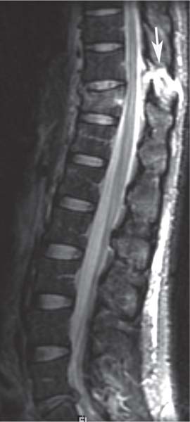
Fig. 11.5 A sagittal STIR image showing a T11 flexion-distraction injury with compression fracture of T11 and an associated injury of the interspinous and supraspinous ligaments, as evidenced by increased signal intensity in the interspinous and supraspinous region between T10 and T11 (arrow).
• Burst fractures
• Disc pathology
• Epidural hematoma
• Vertebral translation or dislocation
• Penetrating trauma (Fig. 11.6)
Burst Fracture
Although CT is excellent in assessing the osseous component of a burst fracture, the associated neural compression and hematoma may be difficult to assess on CT, and MRI is far more accurate. It is important to differentiate a burst fracture (Fig. 11.7) from a compression fracture (Fig. 11.2). The former involves injury to the anterior and middle columns, whereas the latter involves injury to the anterior column only. The MR images should be carefully evaluated for the absence or presence and degree of stenosis, which can be secondary to the fracture alone or to preexisting degenerative changes, or to any combination thereof. Specifically, the sagittal T2-weighted images should be evaluated in the midline for the degree of posterior vertebral body wall encroachment on the spinal canal, CSF column, spinal cord, or cauda equina. Next, the parasagittal images should be evaluated for the same. Finally, the axial T2-weighted images can be reviewed to determine the location and degree of neural compromise in an orthogonal plane.
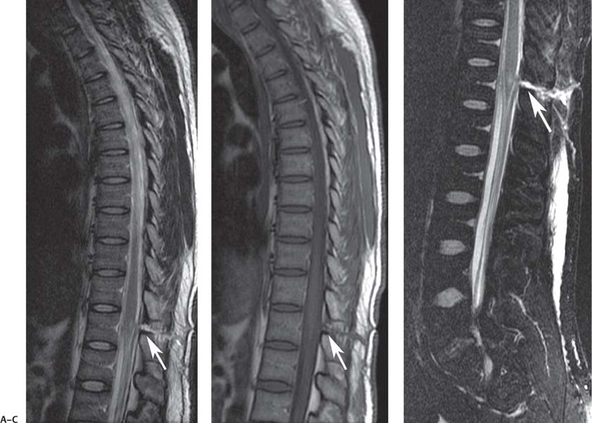
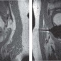
Fig. 11.6 Cord injury from a stab injury to the conus medullaris. (A) A sagittal T2-weighted image of the thoracic spine showing a linear track (arrow) from the skin to the conus medullaris with an associated region of increased signal within the conus medullaris, compatible with edema. (B) A sagittal T1-weighted image of the thoracic spine also showing the track (arrow) but not showing the edema within the conus medullaris. (C) A sagittal STIR image of the lumbar spine accentuates the edema along the track (arrow) and also that within the conus medullaris.
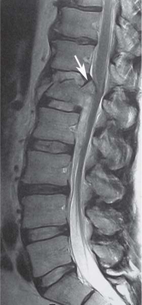
Fig. 11.7 A sagittal T2-weighted image showing an L1 burst fracture. Note that the posterior-superior margin of the vertebral body has displaced and rotated into the spinal canal. This displaced and rotated fragment (arrow) has been termed the sentinel or culprit fragment.
Disc Pathology
Traumatic compressive forces on the disc may lead to annular tears (also known as annular fissures), disc protrusions, extrusions, and sequestrations. Rupture of a few annular fibers leads to a small amount of fluid tracking from the nucleus pulposus to between the annular fibers, leading to a focus of high intensity on T2-weighted images. This finding of focal high intensity in the annulus is referred to as a high-intensity zone (Fig. 11.8) and is suggestive of an annular tear. Although this finding may be seen in association with trauma, its level of importance is controversial because it is also seen as a natural process of disc degeneration and may or may not be associated with acute pain.16–18 MRI is the modality of choice for assessing such abnormalities and associated areas for potential neurologic compromise (see Degenerative Disc Disease, below). The sagittal and axial T2-weighted images should be carefully evaluated for the presence of disc pathology such as protrusion, extrusions, and sequestrations. If present, the degree of neural compromise should be noted (see below).
Epidural Hematomas
Hematomas may occasionally be seen in association with thoracolumbar spine trauma, and they can be difficult to differentiate from disc protrusions and extrusions. Hematomas often resolve spontaneously and may provide an explanation for patients who show a rapid and spontaneous resolution of apparent disc herniations.19–21 Key differentiating features between a disc extrusion and hematoma or fluid collection are a hematoma’s larger size, different signal, obtuse margin along the posterior aspect of the vertebral body with maximum dimension at midvertebral body level, and possible containment by the central septum (which attaches the posterior longitudinal ligament to the vertebral body).22,23
The signal pattern associated with epidural hemorrhage is related directly to the state of the oxygenation of the blood that pools in the regions of interest adjacent to the cord. In the acute phase, T1-weighted images show signal that is isointense compared with that of the adjacent spinal cord, and T2-weighted images show heterogeneous areas of increased and decreased signal intensity. During the acute phase, deoxyhemoglobin is the main component of the hematoma. Deoxyhemoglobin appears isointense or slightly low in signal intensity compared with that of the normal spinal cord on T1-weighted images and as a hypointense signal on T2-weighted images. Within 2 to 4 days after injury, T1-weighted and T2-weighted images may show increased signal intensity.15 By 8 to 10 days, the primary component of the hemorrhage is methemoglobin, which is hyperintense on T1-weighted images.24
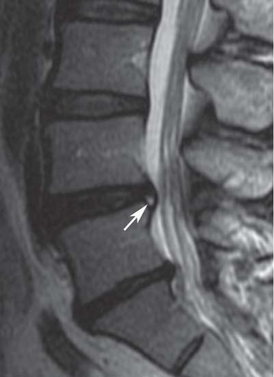
Fig. 11.8 A sagittal T2-weighted image showing a high-intensity zone at the posterior annulus of L4-L5 (arrow). Also noted is degenerative disc disease at L5-S1 with moderate loss of disc height. The L3-L4 disc is normal.
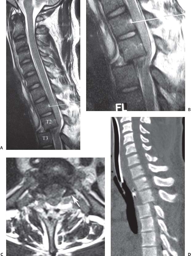
Fig. 11.9 T2-T3 dislocation. This sagittal T2-weighted image (A) and zoom-in (B) show anterior dislocation of T3 relative to T2 without fracture with resultant severe cord compression, deformity, and acute signal change within the cord; the line on each points to the L1 vertebral body. (C) An axial T2-weighted image shows that the facets are “naked” or dissociated, a finding better seen on the left side (arrow). (D) A sagittal reconstructed CT image also shows the dislocation and confirms the absence of a fracture.
Vertebral Translation or Dislocation
The posttraumatic translation of vertebral bodies may produce canal or foraminal narrowing with associated neural compression. Dislocation of the spine indicates an alteration of spinal alignment in all three planes and the displacement of one vertebral body relative to an adjacent one. Typical MRI signs of dislocations include the following:
• Altered facet joint anatomy with increased T2-weighted signal (or fluid) in the facet joints: the osseous anatomy is often better seen on CT, but as mentioned above, edema and fluid on MRI help focus the search for a subtle injury.
• Disc herniation or pseudoherniation: with translation of one vertebral body in relation to the adjacent one, there may be uncovering of the disc, which gives the appearance of a herniation (pseudoherniation).
• Vertebral body translation: sagittal and coronal images are excellent in determining translation of vertebral bodies (Fig. 11.9). Care should be taken in determining if translations are the result of facet degeneration, osseous injury, facet joint displacement, or pars defects.
 Nomenclature and Classification of Lumbar Disc Pathology
The nomenclature used for describing lumbar disc pathology should be consistent and uniformly applied. Fardon and Milette25 provide a comprehensive review of the nomenclature and classification of lumbar disc pathology. This nomenclature and classification scheme represents the recommendations of the combined task forces of the North American Spine Society, American Society of Spine Radiology, and American Society of Neuroradiology. Several other societies, including the American Academy of Orthopaedic Surgery, now support and recommend the use of the nomenclature described below. Surgeons and radiologists involved in the care of patients with known or suspected lumbar disc pathology and the evaluation of their MR images should consider reviewing this publication25 for additional detail.
With this system, disc lesions are classified as follows:
• Normal: a young disc that is morphologically normal (no lesion)
• Congenital/developmental variant: discs that are congenitally abnormal or that have undergone changes in morphology secondary to abnormal growth of the spine
• Degenerative/traumatic lesion: annular tear, degeneration, herniation
• Inflammation/infection: inflammatory spondylitis of subchondral end plate and bone marrow manifested as Modic type 1 MRI changes26–29
• Neoplasia: all pathologic entities that may be primary or metastatic
• Morphologic variant of unknown importance
In the degenerative category, annular tears (also called annular fissures) are separations between annular fibers, avulsion of fibers from their vertebral body insertions, or other injuries of the fibers that involve one or multiple layers of the annular lamellae (Fig. 11.10).
The degenerative process includes desiccation, fibrosis, narrowing of the disc space, diffuse bulging of the annulus beyond the disc space, extensive fissuring, mucinous degeneration of the annulus, defects and sclerosis of the end plates, and osteophytes at the vertebral apophyses. Degenerative changes can also be subcategorized as spondylosis deformans (changes in the disc associated with a normal aging process) and intervertebral osteochondrosis (consequences of a more clearly pathologic process) (Fig. 11.11).
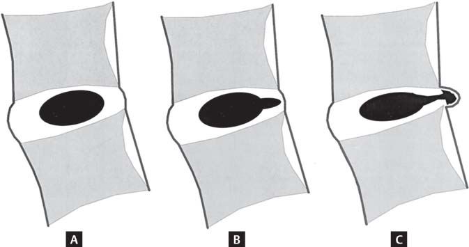
Fig. 11.10 Schematic sagittal drawings showing differentiating MRI features of disc pathology. (A) A normal disc. (B) An annular tear (radial tear, in this case). (C) A disc herniation. The term tear is used to refer to a localized radial, concentric, or horizontal disruption of the annulus without associated displacement of disc material beyond the limits of the intervertebral disc space. Nuclear material is shown in black, and the annulus (internal and external) corresponds to the white portion of the intervertebral space. (From Milette PC. The proper terminology for reporting lumbar intervertebral disc disorders. AJNR Am J Neuroradiol 1997;18:1859–1866. Reprinted with permission.)
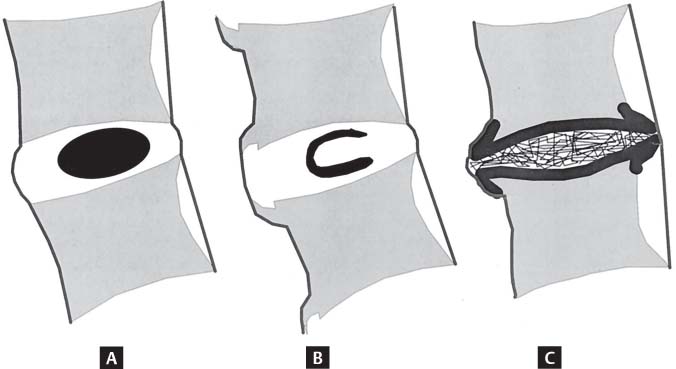
Fig. 11.11 Schematic sagittal drawings showing differentiating disc MRI characteristics. (A) Normal disc. (B) Spondylosis deformans. (C) Intervertebral osteochondrosis. The distinction between these three entities is usually possible on all imaging modalities, including conventional radiographs. (From Milette PC. The proper terminology for reporting lumbar intervertebral disc disorders. AJNR Am J Neuroradiol 1997;18:1859–1866. Reprinted with permission.)
Herniation is defined as a localized displacement of disc contents beyond the borders of the intervertebral disc space (Fig. 11.12A). The disc material may include nucleus, cartilage, fragmented apophyseal bone, or annular tissue, or a combination of those materials. Most clinicians tend to describe disc pathology using the terms bulge, herniation, extrusion, and sequestration. Although the last two terms are often used correctly, there seems to be a high degree of interobserver variability in the use of the first two terms.
The currently accepted nomenclature is as follows: A herniation is considered “localized” if it involves ≤50% of the disc circumference and “generalized” if it involves >50%. A localized displacement is considered “focal” if <25% of the disc circumference is involved (Fig. 11.12B) and “broad-based” if the herniating disc content is between 25% and 50% (Fig. 11.12C). Disc tissue noted circumferentially, between 50% and 100%, and beyond the edges of the ring apophyses is termed bulging, which is not considered by some to be a form of herniation (Fig. 11.12D). The terms protrusion (Fig. 11.12E) and extrusion (Fig. 11.12F) are also commonly used in the context of disc herniation. A protrusion is present if the greatest distance between the edges of the disc material beyond the disc space is less than the distance between the edges of the base in the same plane. The base is the cross-sectional area of disc material at the outer margin of the disc space of origin, where disc material displaced beyond the disc space is continuous with disc material within the disc space. An extrusion is present when any one distance between the edges of the disc material beyond the disc space is greater than the distance between the edges of the base (Fig. 11.13) or when there is no continuity between the disc space and the disc fragment. Extrusion may be further classified as sequestered and migrated. Sequestration is noted if the displaced disc material is completely discontinuous with the parent disc. Migration refers to displacement of disc material away from the site of extrusion, regardless of whether or not there is sequestration (Fig. 11.14).
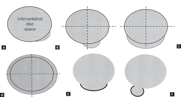
Fig. 11.12 In disc herniation, the interspace is defined, peripherally, by the edges of the vertebral ring apophyses, exclusive of osteophytic formations. (A) Localized extension of disc material beyond the intervertebral disc space, in a left posterior direction, which qualifies as a disc herniation. (B) By convention, a focal herniation involves <25% (90 degrees) of the disc circumference. (C) By convention, a broad-based herniation involves between 25% and 50% (90 to 180 degrees) of the disc circumference. (D) Symmetrical presence (or apparent presence) of disc tissue “circumferentially” (50% to 100%) beyond the edges of the ring apophyses may be described as a “bulging disc” or “bulging appearance” and is not considered a form of herniation. Bulging is a descriptive term for the shape of the disc contour and not a diagnostic category. (E) Protrusion (see definition in text). (F) Extrusion (see definition in text). (From Fardon DF, Milette PC. Nomenclature and classification of lumbar disc pathology. Recommendations of the Combined Task Forces of the North American Spine Society, American Society of Spine Radiology, and American Society of Neuroradiology. Spine 2001;26:E93–E113. Reprinted with permission.)
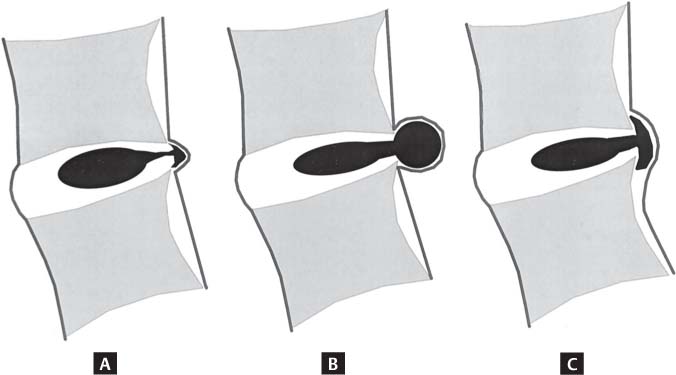
Fig. 11.13 Protrusion and extrusion. When a relatively large amount of disc material is displaced, distinction between protrusion (A) and extrusion (B,C) is usually possible only on sagittal MR sections or sagittal CT reconstructions. (C) Although the shape of the displaced material is similar to that of a protrusion, the greatest craniocaudal diameter of the fragment is greater than the craniocaudal diameter of its base at the level of the parent disc, and the lesion therefore qualifies as an extrusion. In any situation, the distance between the edges of the base, which serves as reference for the definition of protrusion and extrusion, may differ from the distance between the edges of the aperture of the annulus, which cannot be assessed on CT images and is seldom appreciated on MR images. In the craniocaudal direction, the length of the base cannot exceed, by definition, the height of the intervertebral space. (From Milette PC. Classification, diagnostic imaging, and imaging characterization of a lumbar herniated disc. Radiol Clin North Am 2001;38:1267–1292. Reprinted with permission.)
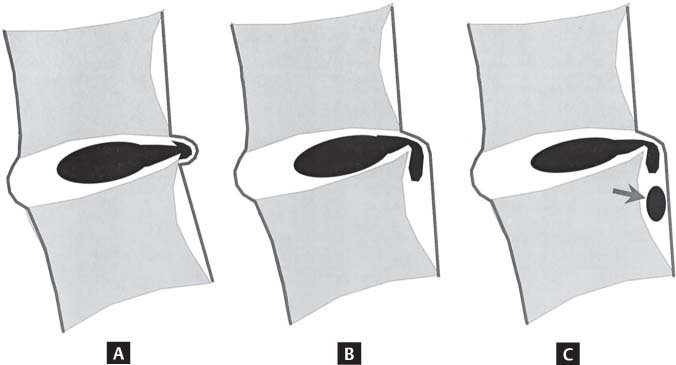
Fig. 11.14 Schematic representations of various types of posterior central herniations. (A) A small subligamentous herniation (or protrusion) without substantial disc material migration. (B) A subligamentous herniation with downward migration of disc material under the posterior longitudinal ligament. (C) A subligamentous herniation with downward migration of disc material and sequestered fragment (arrow). (From Milette PC. Classification, diagnostic imaging, and imaging characterization of a lumbar herniated disc. Radiol Clin North Am 2001;38:1267–1292. Reprinted with permission.)
 Degenerative Conditions
Along with cervical degenerative disorders, lumbar degenerative disc disease and the associated stenosis are the most common indications for MRI of the spine. Most patients present with low back pain, lower extremity pain, or symptoms of neurogenic claudication. They usually have had at least 6 weeks of unsuccessful nonoperative management and often have already been evaluated with conventional radiography. The purpose of MRI in this situation is most frequently to evaluate for the presence or absence of spinal stenosis, disc herniation, and degenerative disc disease.
Lumbar spine degeneration typically includes a constellation of changes, such as degenerative disc disease, arthritic and hypertrophic changes involving the facet joints, and hypertrophy of the ligamentum flavum (see Chapter 10 for a discussion of inflammatory arthropathies, including anky-losing spondylitis). It is important to note that patients exhibiting MRI changes may not necessarily be symptomatic.30 A study of 33 asymptomatic, elite tennis players showed that 15.2% had a normal MRI evaluation and 84.8% had abnormalities: 27.3% had pars lesions and 39.4% showed evidence of disc desiccation and bulging.30 The high incidence of abnormal lumbar spine MRI studies was described by Boden et al.31 in 67 asymptomatic patients. A follow-up study of those 67 patients concluded that the MRI findings were not predictive of the development or duration of low back pain.32
Disc and End Plates
Degenerative Disc Disease
As noted above, Fardon and Milette25 have suggested the use of the terms normal, spondylosis deformans, and intervertebral osteochondrosis to describe the degenerative lumbar disc (Fig. 11.11). The specific changes seen on MRI correlate with the pathogenesis of degenerative disc disease, which results from the spectrum of changes that occur in the various parts of the vertebrodiscal complex. The nucleus pulposus becomes increasingly hypointense on T2-weighted images because of desiccation. An alternative finding is the intervertebral disc vacuum phenomenon secondary to a collection of intradiscal nitrogen, which manifests as a linear area of signal void on T1-weighted and T2-weighted sequences. Gradient-echo sequences may show this particular finding even better than do T1-weighted and T2-weighted images.33 Early signs of disc degeneration on MRI include infolding of the anterior annulus and a hypointense central region often seen before any loss of disc signal intensity, which may be associated with reproduction of pain at discography.33 Advanced degeneration may present with a linear hyperintensity parallel to the end plate, which is thought to represent separation of the nucleus pulposus from the hyaline cartilage end plate.33
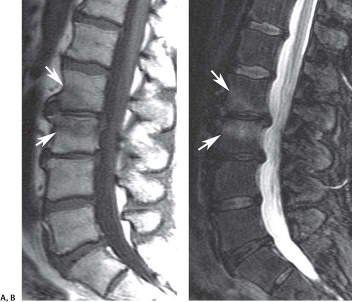
Fig. 11.15 Modic type 1 (fibrovascular) changes. Sagittal T1-weighted (A) and fat-suppressed T2-weighted (B) images showing the typical pattern (arrow on each) of decreased signal intensity on the T1-weighted image and increased signal on the T2-weighted image at the L2-L3 level that is seen with Modic type 1 end-plate changes.
Pfirrmann et al34 introduced a grading system for lumbar degenerative disc disease based on MRI findings on sagittal T2-weighted images. This classification system, which describes five grades of progressively increasing degenerative disc disease, is complex, which may be the reason it is not commonly used by most clinicians. To summarize, the grading system describes the lumbar disc degenerative process as a continuum that progresses from a normal disc, to loss of the normal disc signal on T2-weighted images, to increasing loss of disc height, to degenerative end-plate changes and sclerosis.
Modic et al.26,29 described signal changes within the vertebral body bone marrow and end plate adjacent to degenerating discs. The first finding in the sequence of changes is fibrovascular ingrowth that results in diminished signal intensity on T1-weighted images and a corresponding increase in signal intensity on T2-weighted images (type 1) (Fig. 11.15). The more chronic, type 2 changes involve a change from hematopoietic (red) to fatty (yellow) marrow, leading to relatively increased signal on T1-weighted images and slightly diminished signal intensity on T2-weighted images (Fig. 11.16). Type 3 changes consist of decreased signal intensity on T1-weighted and T2-weighted sequences and are associated with subchondral sclerosis on radiographs27,33 (Fig. 11.17). Among the three types of degenerative end-plate changes, type 1 changes have been found to have the greatest correlation with the presence of discogenic back pain.28,35,36
In addition to an assessment of the type of lumbar degenerative disc disease using the methods described above, one should also describe the degree of lumbar disc degeneration by noting the amount of disc space height loss (Fig. 11.18).
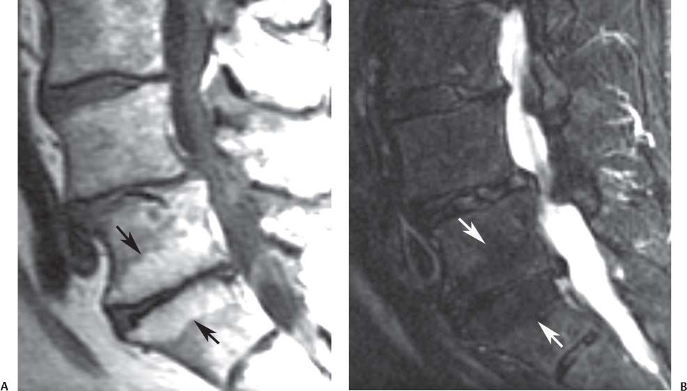
Fig. 11.16 Modic type 2 (fatty) changes. Sagittal T1-weighted (A) and fat-suppressed T2-weighted (B) images showing the typical pattern (arrows on each
Related posts:
Stay updated, free articles. Join our Telegram channel

Full access? Get Clinical Tree


