FIG. 11.1 Supporting ligamentous structures of craniovertebral junction posterior view.The posterior arch of C1 has been removed. (From Weinstein JS, Nemecek AN. Trauma-related complications—atlantooccipital dislocation. In: Benzel EC, ed. The Cervical Spine. 5th ed. Philadelphia, PA: Lippincott Williams & Wilkins; 2012:1247–1255.)
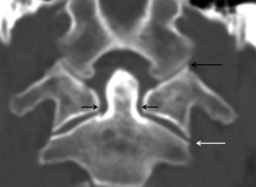
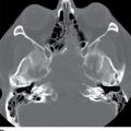
FIG. 11.2 Normal craniovertebral anatomy.Coronal CT reformation. The occipital condyles and C1 lateral masses articulate without offset (long black arrow). The lateral masses of C1 should be parallel and align with the lateral masses of C2 without offset (white arrow). The lateral atlantodental interval should be uniform (short black arrows).
Atlantoaxial dissociation
AAD is abnormal displacement at the atlantoaxial articulation and can be due to ligamentous and/or bony injury. AAD is one of the most confusing injury classifications as it has overlap with atlantoaxial instability and torticollis (discussed below). Normally, the transverse atlantal ligament (TAL) prevents anterior translation of the atlas on the axis and, in combination with the facet capsules, maintains the integrity of the C1-C2 joint. Congenital conditions may predispose to AAD, such as Down syndrome with ligamentous laxity. Following traumatic injury, the atlas and axis may become rotationally fixed, and patients present with a characteristic flexed neck with the head tilted to one side and rotated to the other. This type of injury is rare and is associated with multiple mechanisms including flexion–extension, distraction, or rotation at C1-C2. Four types of AAD have been described with variable degrees of dislocation and involvement of the transverse atlantal and alar ligaments (Table 11.1).
Table 11.1 Classification of Atlantoaxial Dissociation

AAD may be suspected on plain radiographs (or sagittal CT-reformatted images) if the anterior atlantodental interval exceeds 3 mm on a well-positioned lateral projection. Axial CT demonstrates excessive rotation of the atlas on the axis, which exceeds the physiologic 45 degrees (Fig. 11.3B). The reformatted coronal CT view can assess the lateral displacement of the lateral masses of C1 on C2 (Fig. 11.3A). If the combined spread of the lateral masses is greater than 7 mm, injury to the transverse ligament is likely. MRI in AAD can show ligamentous injury and soft tissue edema (Fig. 11.3C).
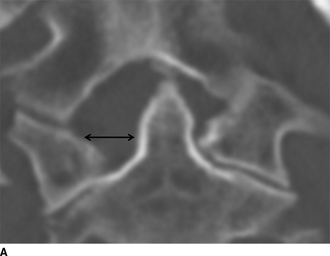
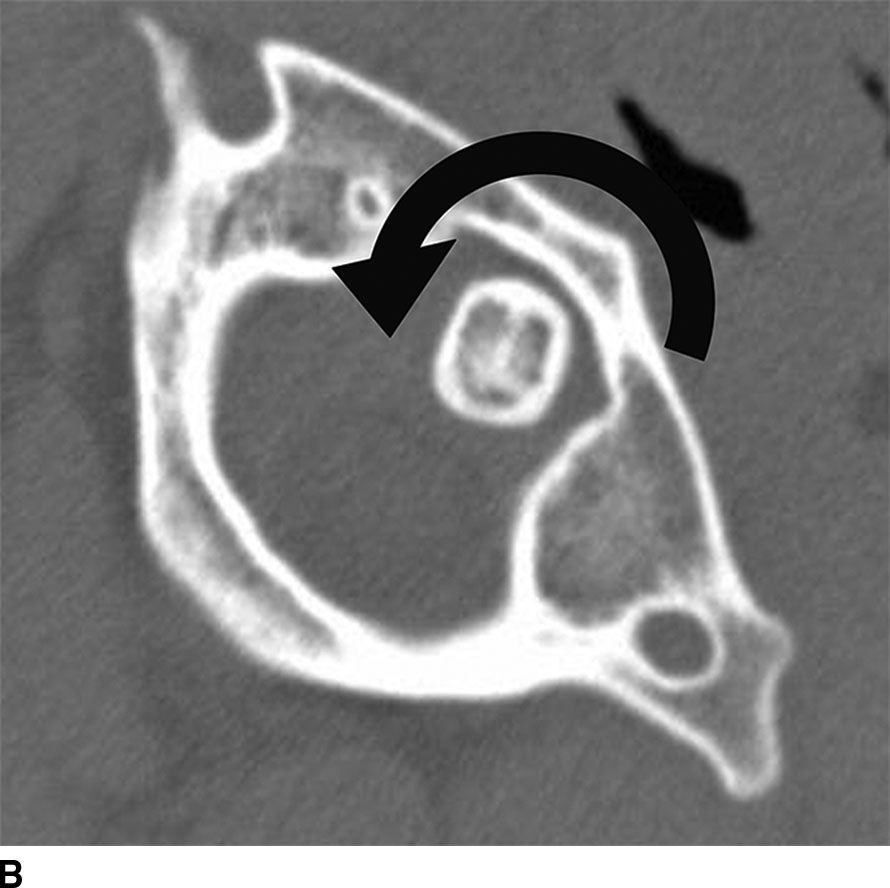
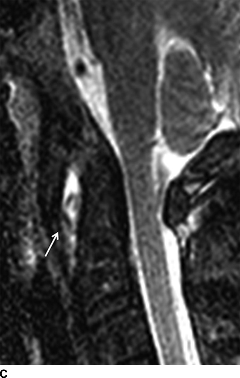
FIG. 11.3 Atlantoaxial dissociation. A. Coronal CT reformation. Asymmetric widening of the right atlantodental interval (arrow). B. Axial CT shows that C1 is abnormally rotated (arrow) on C2 without anterior displacement. C. Sagittal STIR MRI shows increased signal in the predentate space (arrow) indicating ligamentous injury. There is also increased signal in the ligaments between the posterior elements of C1 and C2.
Lateral tilt and rotation of the head can also be the presenting features of a more benign process such as torticollis and must be differentiated from AAD injuries. In cases where torticollis cannot be differentiated from AAD, dynamic CT can be performed with voluntary head turning to the left and right. Patients with AAD will have rotatory fixation and will not demonstrate reduction and reversal of the subluxation with head turning (8). Note that the TAL may also be injured in other fracture patterns such as in axial loading injury where the attachment of the TAL to the lateral mass of C1 is avulsed.
Atlanto-occipital dislocation
AOD injuries usually result from high-speed MVAs and are often clinically devastating due to associated head and visceral comorbidities. When there is complete separation of the occipital condyles from the lateral masses of the atlas, this causes complete disruption of all of the associated supporting ligamentous structures. The distractive forces can stretch the brainstem causing respiratory compromise and death. The three recognized mechanisms of injury include superior and anterior displacement of the cranium relative to C1 (most common), pure superior displacement of the cranium, and posterior dislocation of the cranium relative to C1.
A radiographic measurement for diagnosing AOD is the basion–axial interval (BAI) (9). The BAI is obtained by drawing a vertical line along the posterior margin of the C2 vertebral body and a horizontal line through the tip of the basion (Fig. 11.4). Normally, the measurement between the two lines should be less than 12 mm in adults where greater values suggest AOD (Fig. 11.5). An additional useful measurement is the basion–dental interval (BDI). This is obtained by drawing a straight connecting line between the most inferior portion of the basion and the most superior portion of the dens. Normal measurements are also less than 12 mm (10).
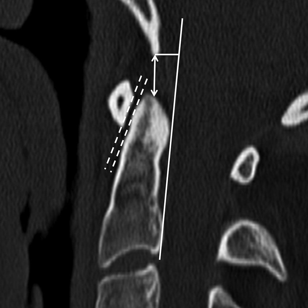
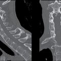
FIG. 11.4 Normal craniocervical measurements.Sagittal reformatted CT shows basion–axial interval (solid horizontal line) as the distance between a line extended superiorly along the posterior margin of C2 (solid vertical line) and the tip of the basion and should measure less than 12 mm. Basion–dental interval (arrow) is the distance between the basion and superior margin of the dens and should measure less than 12 mm. Atlantodental interval (dashed lines) is the distance between the posterior margin of the anterior arch of C1 and anterior margin of the dens and should measure less than 3 mm.
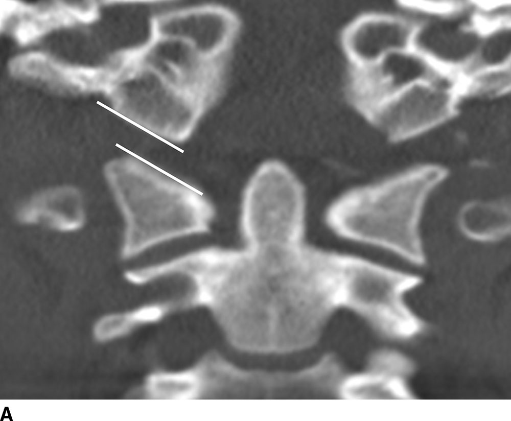
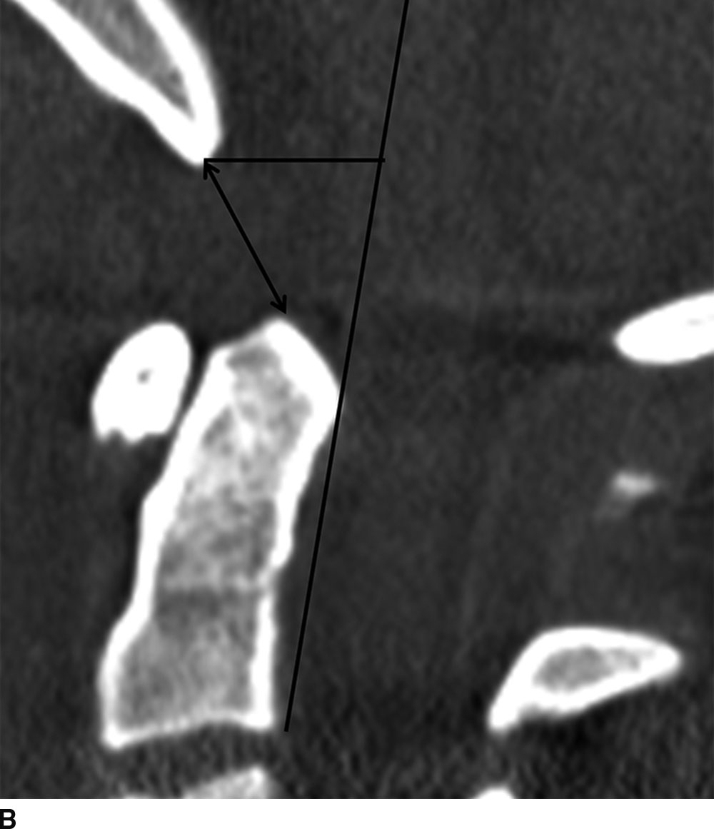
FIG. 11.5 Abnormal craniovertebral intervals.Coronal (A) and sagittal (B) reformatted CT images show a widened atlanto-occipital articulation (lines in A) and abnormally widened basion–axial (horizontal line in B) and basion–dental (arrow in B) intervals.
Occipital condyle fracture
Once regarded as rare injuries, occipital condyle fractures are increasingly recognized due to widespread use of MDCT in the evaluation of trauma. A missed or delayed diagnosis of occipital condyle fracture can have significant consequences because it is often the only osseous feature associated with significant damage to the craniocervical ligamentous complexes with resultant instability. MDCT is the best method to assess for occipital condylar fractures as the findings can be subtle and are not reliably detected with radiography (Fig. 11.6; Table 11.2). In the setting of occipital condyle fractures, the assessment of ligamentous injury with MRI helps determine treatment (11).
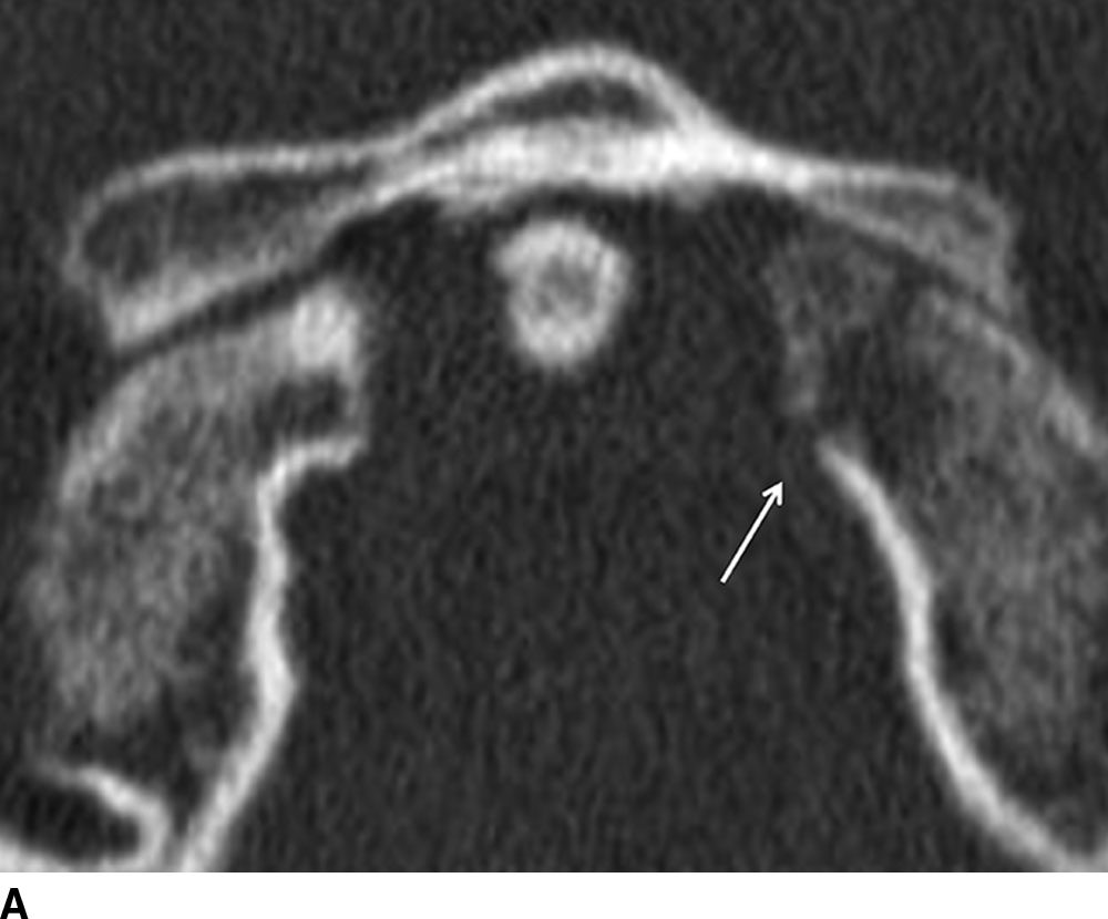
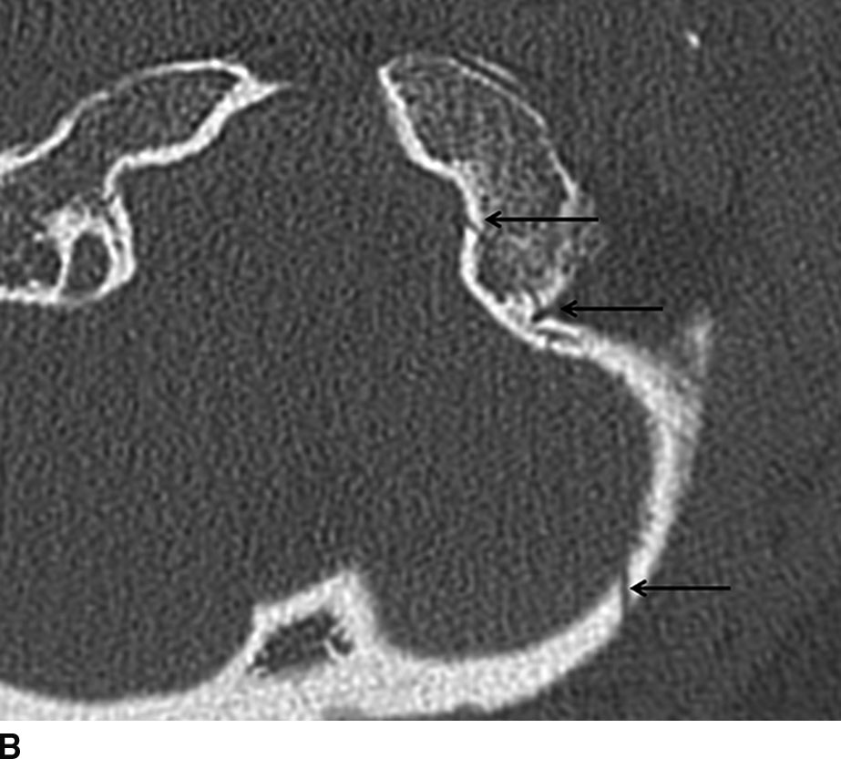
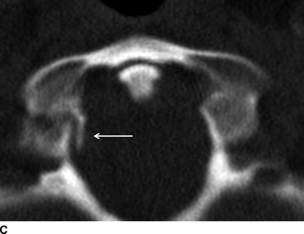
FIG. 11.6 Occipital condyle fractures. A: Axial CT shows a type I left occipital condyle fracture with minimal displacement (arrow). B: Axial CT shows a type II occipital condyle fracture with a linear fracture through the occipital bone that extends anteriorly to involve the left occipital condyle (arrows). C: Axial CT shows medially displaced fracture of the right occipital condyle, consistent with a type III occipital condyle fracture (arrow). Medial fracture fragment displacement results from an intact alar ligament.
Table 11.2 Classification of Occipital Condyle Fractures
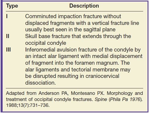
Adapted from Anderson PA, Montesano PX. Morphology and treatment of occipital condyle fractures. Spine (Phila Pa 1976). 1988;13(7):731–736.
C2 or axis fractures
Fractures of the odontoid process are the most common cervical spine fractures. Three types of fractures are well recognized as described by Anderson and D’Alonzo (12) (Table 11.3). Open-mouth odontoid frontal plain films and coronal CT images are best for diagnosis of type I and type II fractures, which demonstrate fracture lines traversing the superolateral dens tip (type I) or base of the odontoid (type II) (Fig. 11.7). Type III fractures (with fracture lines through the base of the odontoid and the body of C2) are better visualized on the lateral projection or on reformatted CT images (Fig. 11.8). A “fat C2” sign has also been described, which is an increase in the anteroposterior length of the C2 vertebral body compared with the length of C3. The increased C2 length represents an oblique displaced fracture of the C2 body (13).
Table 11.3 Classification of Odontoid Fractures
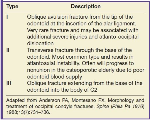
Adapted from Anderson PA, Montesano PX. Morphology and treatment of occipital condyle fractures. Spine (Phila Pa 1976) 1988;13(7):731–736.
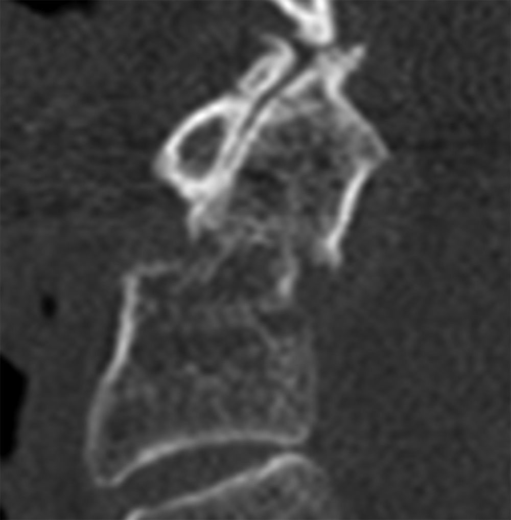
FIG. 11.7 Type II dens fracture.Sagittal reformatted CT demonstrates a type II dens fracture with transverse fracture through the base of the dens with mild posterior displacement.
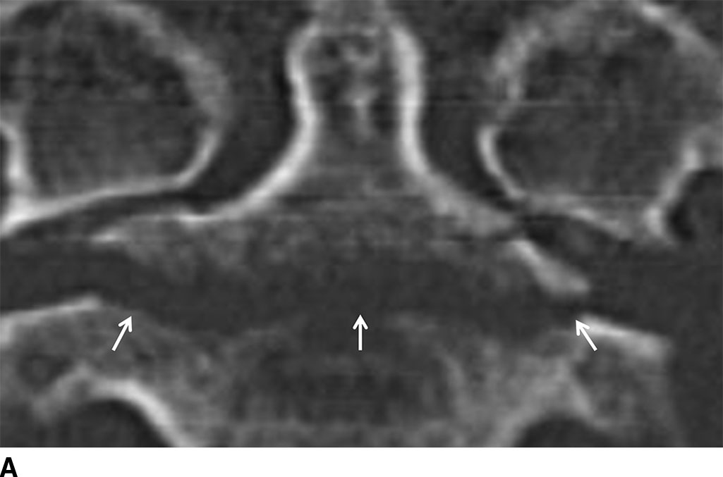
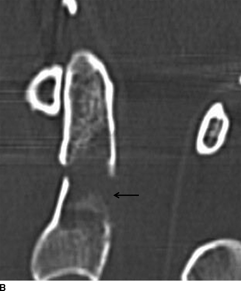
FIG. 11.8 Type III dens fracture.Coronal (A) and sagittal (B) reformatted CTs show a type III dens fracture (arrows in A) through the body of the axis. The dens is mildly angulated anteriorly (arrow in B).
An os odontoideum, thought to be an ossified cartilaginous dens fracture during childhood, may be confused with a displaced dens fracture (Fig. 11.9). Well-corticated smooth margins distinguish an os odontoideum from a fracture.
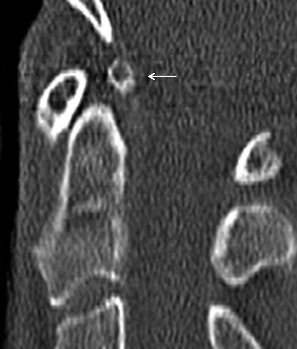
FIG. 11.9 Os odontoideum.Sagittal reformatted CT. Well-defined ossicle (arrow) at the dens tip representing an orthotopic os odontoideum.
Hangman fracture
Traumatic spondylolisthesis of the axis, or hangman fracture, results from hyperextension with axial loading or forced hyperflexion with axial loading. The fracture anatomically occurs in the isthmus or pars interarticularis of C2 rather than the pedicles, and the fractures may involve the C2 body (Figs. 11.10 and 11.11). This fracture is decompressive, widening the diameter of the central canal at the C2 level, and therefore, neurologic injury is typically absent. The Effendi classification is used for this fracture (Table 11.4) (14). Reformatted sagittal CT images are helpful in assessing for subtle offset of the spinolaminar line, which may be a sign of posterior vertebral body displacement.
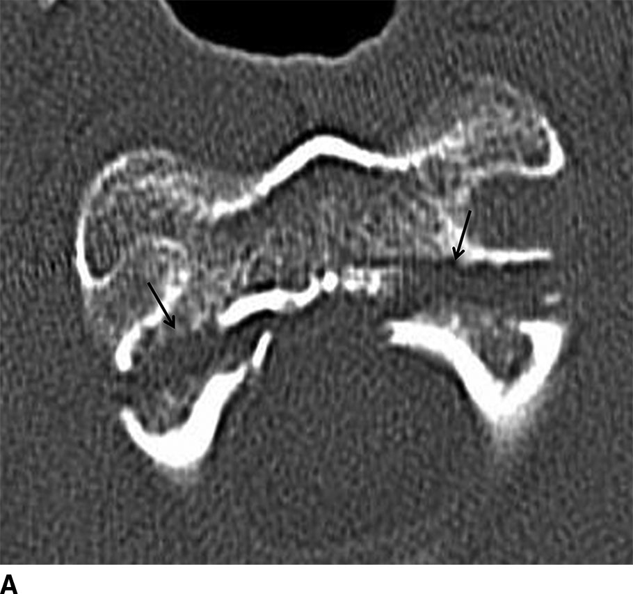
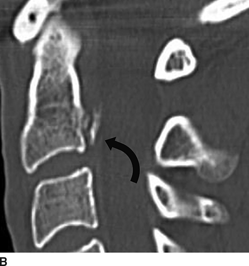
FIG. 11.10 Type I hangman’s fracture. A: Axial CT through C2 shows fractures through the bilateral pars interarticularis (arrows) with minimal posterior displacement. B: Sagittal reformatted CT shows the fracture fragment (arrow) posterior to the C2 vertebral body.
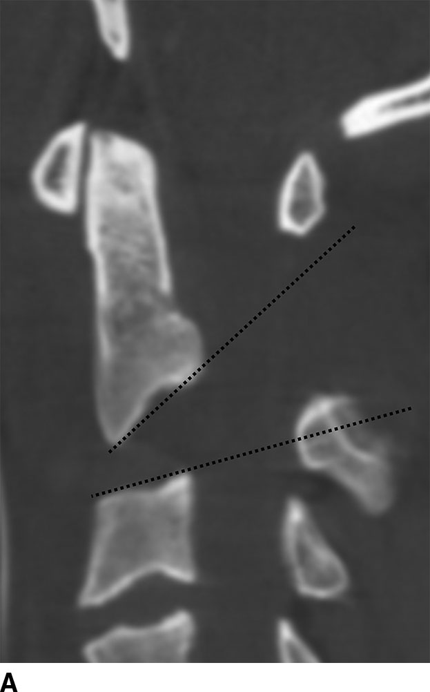
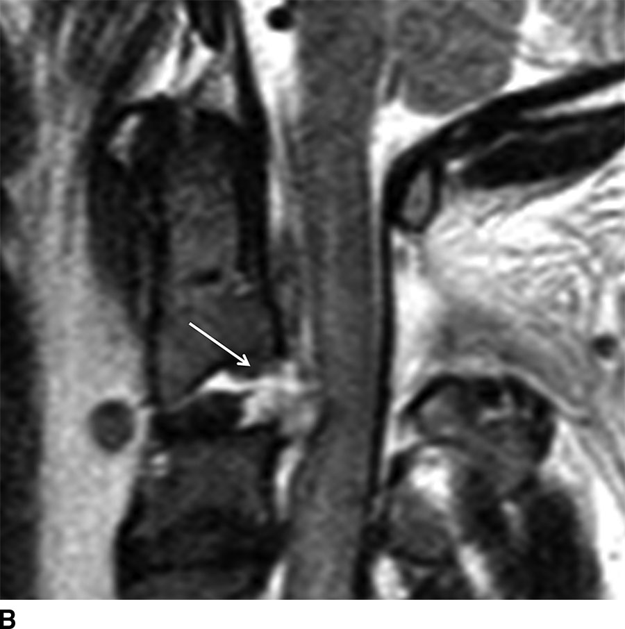
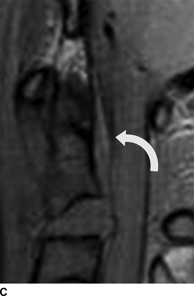
FIG. 11.11 Type IIa hangman’s fracture. A: Sagittal reformatted CT shows marked angulation of C2 with a posteriorly widened C2-C3 disk space (lines). B: Sagittal fat-saturated FSE T2-weighted image shows acute herniation of disk material (arrow) into the ventral epidural space causing cord compression. There is marked prevertebral edema and edema within the spinal cord and posterior ligamentous complex. C: Gradient-echo image demonstrates a small amount of epidural hemorrhage (arrow) dorsal to C2.
Table 11.4 Effendi Classification of Traumatic Spondylolisthesis of C2
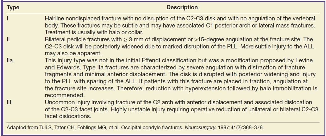
Adapted from Tuli S, Tator CH, Fehlings MG, et al. Occipital condyle fractures. Neurosurgery. 1997;41(2):368–376.
Axial loading injuries
A burst fracture of the atlas is typically caused by an axial loading force (diving injury) to the cranium and is called a Jefferson fracture. The occiput compresses the occipital condyles with force then transmitted to the sloped lateral masses of C1 causing radial displacement of the fracture fragments away from the spinal canal. Although classically described as having two fractures of the anterior arch and two fractures of the posterior arch, it is more common to observe two fractures of the posterior arch and one off-center fracture in the anterior arch and variants (10). Neurologic injury is rare due to the decompressive nature of the injury (9). Treatment is dependent on degree of displacement of fracture fragments and status of the TAL (14).
All three orthogonal planes on CT will demonstrate the features of this injury including widening of the atlantoaxial interval and displacement of the lateral masses symmetrically (Fig. 11.12). If there is greater than 7 mm of combined offset of the lateral masses, the fracture should be considered unstable (10). Axial CT will frequently show all of the fractures in a single image if the plane of section is parallel to C1.
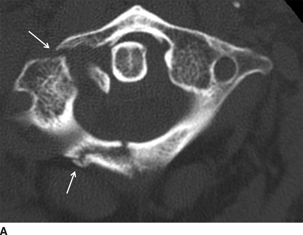
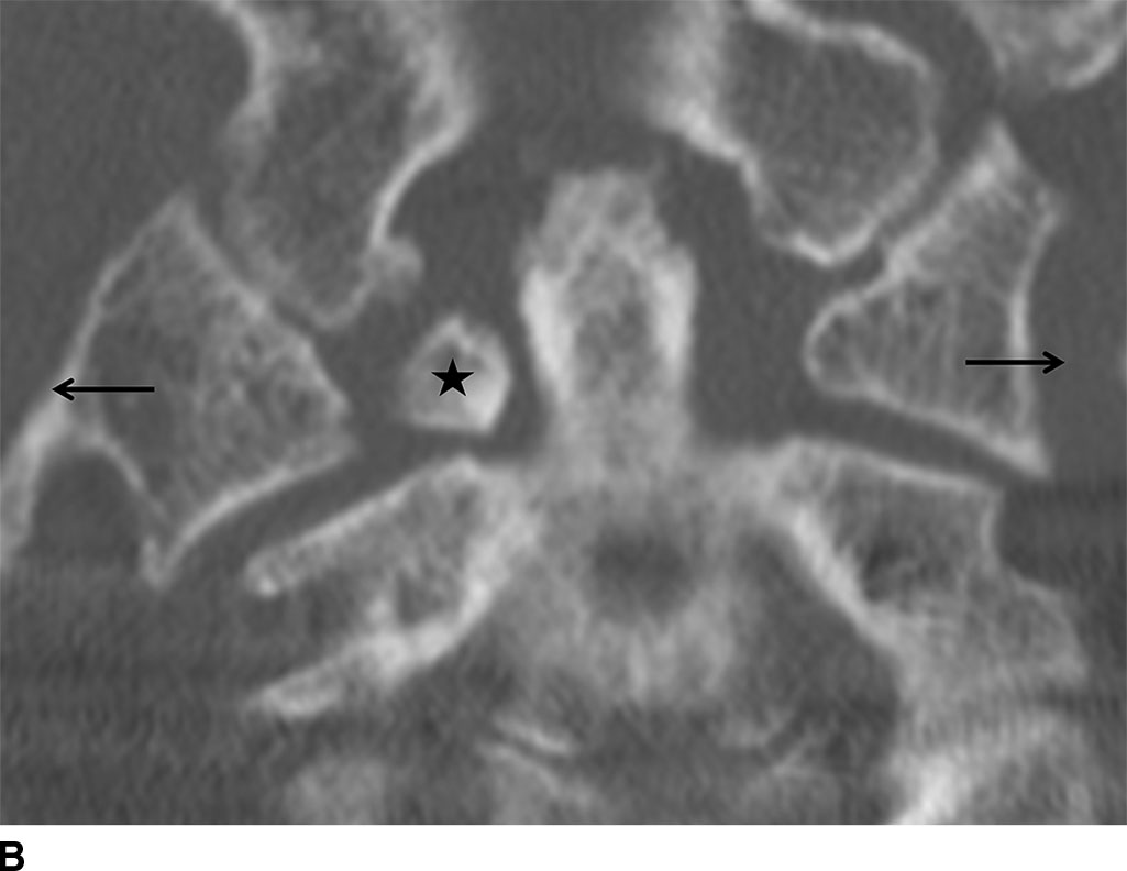
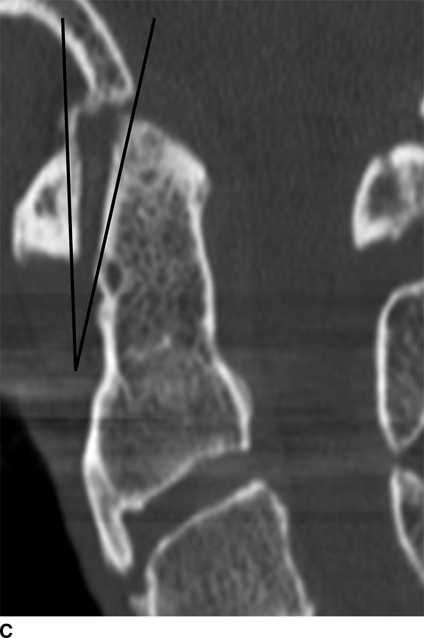
FIG. 11.12 Jefferson fracture. A: Axial CT shows fractures of the right anterior and posterior arches of C1 and the right lateral mass of C1 (arrows) with mild displacement. B: Coronal reformatted CT shows offset of the lateral masses (arrows) of C1 on C2 and a displaced fracture fragment adjacent to the dens (star). C: Sagittal CT reformat shows a V sign, as an increased angle between the superior–posterior margin of C1 and the superior–anterior margin of the dens (15).
Lower cervical injuries
Injuries to the lower cervical spine may be classified by mechanism, including hyperflexion, hyperextension, rotation, lateral strain, and shear forces. The majority of injuries in the lower cervical spine are due to hyperflexion mechanisms.
Hyperflexion injury
Hyperflexion sprain is the mildest form of a pure hyperflexion injury and results from strain or failure of the posterior longitudinal ligament (PLL) and of posterior ligamentous complex (PLC), including the ligamentum flavum (LF), and supraspinous and interspinous ligaments (16). Purely ligamentous injury may result from a hyperflexion mechanism, such as in the case of rear-end MVA-related whiplash in which the head first flings backward and then recoils forward (hyperextension with hyperflexion recoil). In a pure hyperflexion strain, the PLC is disrupted, while in the case of anterior subluxation, the PLC and PLL are both injured, and there is a concomitant annular fissure allowing the superior vertebral body to anteriorly translate. Distinction between these two entities is important since purely ligamentous injury is stable, while anterior subluxation, if undiagnosed, may result in delayed instability.
On lateral radiographs and sagittal reformatted CT images of hyperflexion sprain/anterior subluxation, there is focal kyphotic angulation with narrowing of the anterior and widening of the posterior disk space (Fig. 11.13). Other features include widening of the interspinous space and uncovering of the superior articular process of the facet articulation indicating subluxation of the apophyseal joint (17). The amount of subluxation is generally small (less than 3 mm). MRI is particularly helpful when evaluating hyperflexion sprain/anterior subluxation. Edema is present within the PLC, and the posterior aspect of the disk interspace may reveal an annular fissure and discontinuity of the PLL.
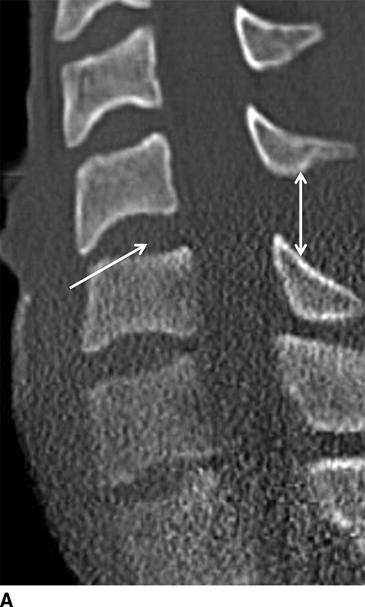
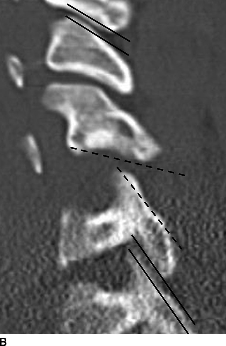
FIG. 11.13 Hyperflexion sprain. A: Sagittal reformatted CT images show focal kyphosis with widening of the posterior disk space (single arrow) and widening of the interspinous space (double arrow). B: Parasagittal reformatted CT shows uncovering of the facets (dashed lines). Note the normal-appearing facets above and below the level of injury (solid lines) lined up as “shingles on a roof.”
Simple wedge compression fracture is a hyperflexion injury with cortical disruption of the anterior aspect of the superior endplate due to the contribution of an additional axial loading force from the superiorly adjacent vertebral body. Fractures do not extend beyond the endplate, and there is less than 25% loss of vertebral body height (Fig. 11.14). The injury is considered stable if the posterior half of the vertebral body is preserved and there are no signs of injury to the PLC.
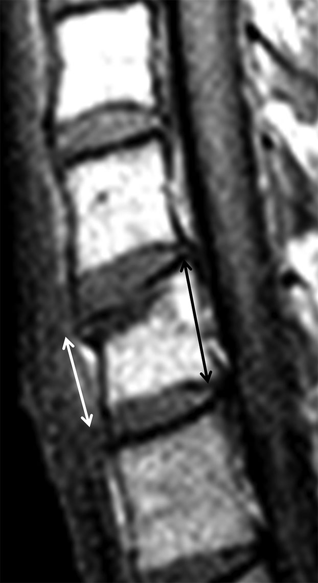
FIG. 11.14 Simple wedge compression fracture.Sagittal T1-weighted images shows mild wedge compression fracture of the superior endplate of C7 with hypointense marrow replacement (edema) at the superior end plate. Wedging is due to loss of anterior vertebral body height (white arrow) compared to posterior height (black arrow).
Another injury resulting from a pure hyperflexion mechanism is an obliquely oriented fracture through the spinous process of a lower cervical or upper thoracic vertebra (most commonly C7), commonly referred to as a clay shoveler’s fracture. This unique injury pattern occurs when there is abrupt flexion and the musculature of the posterior neck is tensed. This injury is characterized by osseous rather than ligamentous failure. The injury in isolation is considered stable.
The flexion teardrop fracture is the most severe and clinically devastating injury in the hyperflexion category and involves severe flexion and axial load, which can be seen with injuries resulting from diving into shallow water or high-speed MVAs. The lower cervical spine, usually the C5 level, is most commonly affected. Large forces are focally transmitted into a single vertebral body causing it to fail and fragment outward. The hyperflexion teardrop is characterized by a sagittal and coronal split of the body from endplate to endplate (Fig. 11.15). A large triangular fracture occurs at the anteroinferior margin of the vertebral body, and there is associated disruption of the posterior ligament complex, PLL, intervertebral disk, and anterior longitudinal ligament (ALL). There may be subluxation, with fracture and/or dislocation of the facets. The free portion of the posterior cortex retropulses with substantial force resulting in impact on the spinal cord. Clinically, an anterior cord syndrome may result with complete quadriplegia and loss of pain, touch, and temperature sensation but intact position, motion, and vibration due to sparing of the posterior columns.
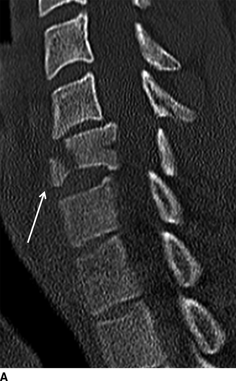
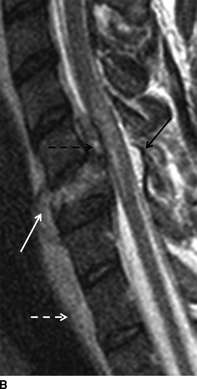
FIG. 11.15 Hyperflexion teardrop fracture. A: Sagittal reformatted CT shows a large triangular fracture fragment (arrow) arising from the anteroinferior C6 vertebral body with retropulsion of the larger fracture fragment into the spinal canal. B: Sagittal T2 FSE shows that the C6 vertebral body fragments are hyperintense due to edema. There is gross disruption of the C5-C6 disk, which has extruded anteriorly (solid white arrow) and posteriorly into the ventral epidural space (dashed black arrow) along with blood products. The ALL and PLL are disrupted. There is flame-shaped edema within the cord and marked prevertebral soft tissue swelling (dashed white arrow). The ligament flavum is also focally disrupted at the level of injury (solid black arrow).
Bilateral interfacetal dislocation (BID) is also a consequence of acute hyperflexion injury in which both inferior articular facets of one vertebral body glide forward and become locked anterior and inferior to the superior articulating facets of the segment below. There is rupture of the facet capsule and occasionally an avulsion fracture of the articular process. A BID is associated with greater than 50% anterolisthesis of the involved vertebral bodies causing marked narrowing of the central canal with spinal cord injury. There may also be traumatic disk herniation and epidural hemorrhage (Fig. 11.16).
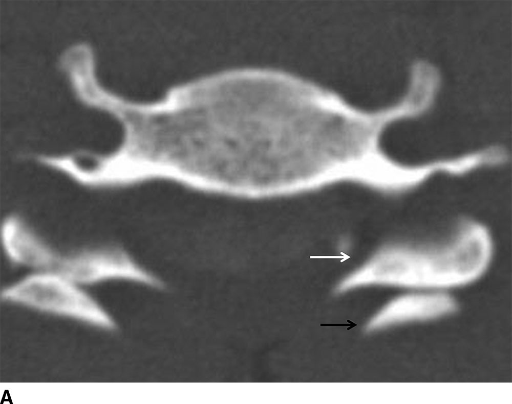
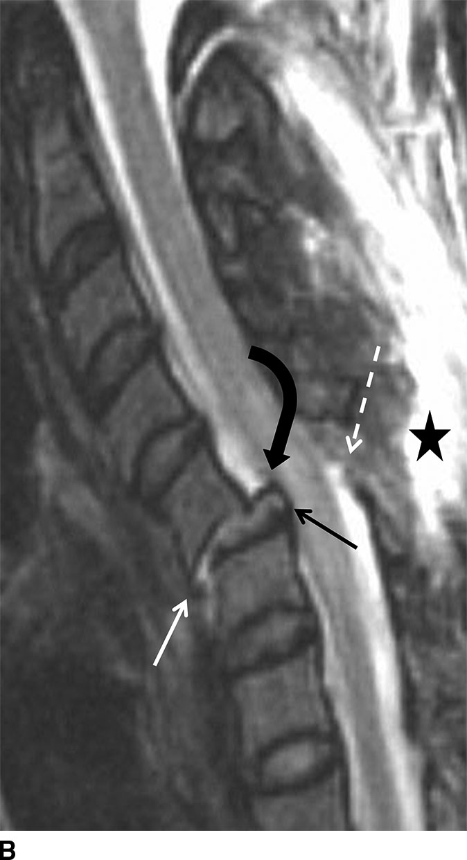
FIG. 11.16 Bilateral facet dislocation. A: Axial CT shows bilateral facet dislocation with both inferior articular facets (white arrow) of the superior vertebral body anteriorly dislocated relative to the superior facets (black arrow) of the inferior vertebral body. B: Sagittal T2 FSE with fat saturation shows nearly 50% C5 to C6 anterolisthesis and disruption of the disk (straight black arrow). The ALL (solid white arrow) is ruptured, and the PLL is markedly stretched (black curved arrow). The LF (dashed white arrow) and posterior ligamentous complex (star) are disrupted.
The combined forces of hyperflexion and rotation can result in dislocation of only one facet joint resulting in a unilateral interfacetal dislocation (UID). In this instance, there will be anterior subluxation of 25% the AP length of the vertebral body. Fractures of the articular facets, pedicles, and lamina are common. This injury is considered stable but is nearly always addressed surgically due to risk of delayed instability.
On plain film or CT, BID or UID results in loss of normal orientation of the facet joints compared to the adjacent levels (Fig. 11.17).
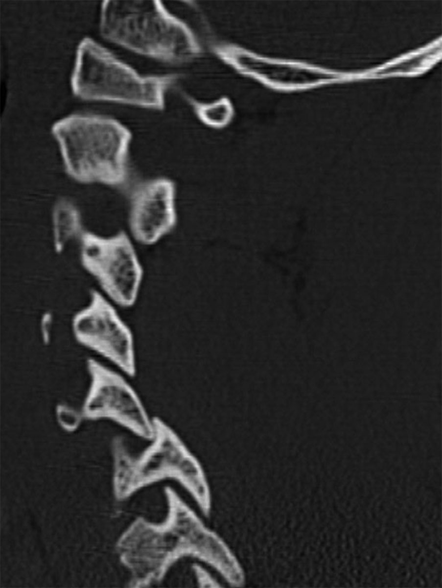
FIG. 11.17 Unilateral facet dislocation.Sagittal reformatted CT shows the inferior articular facet of C5 abnormally positioned anterior to the C6 superior articular facet, implying disruption of the facet capsule.
Extension injuries
Hyperextension injuries result in distraction injuries at the anterior aspect of the cervical spine and compressive injuries posteriorly. Due to the extreme strain placed on the anterior soft tissue structures with hyperextension injuries, prevertebral soft tissue swelling will be seen from injury to the longus colli and longus capitis muscles. The disk space may widen anteriorly due to injury to the ALL (Fig. 11.18). If the force is great enough, there may also be avulsion of the disk from the superior vertebral body and stripping of the PLL from the dorsal surface of the inferior vertebral body.
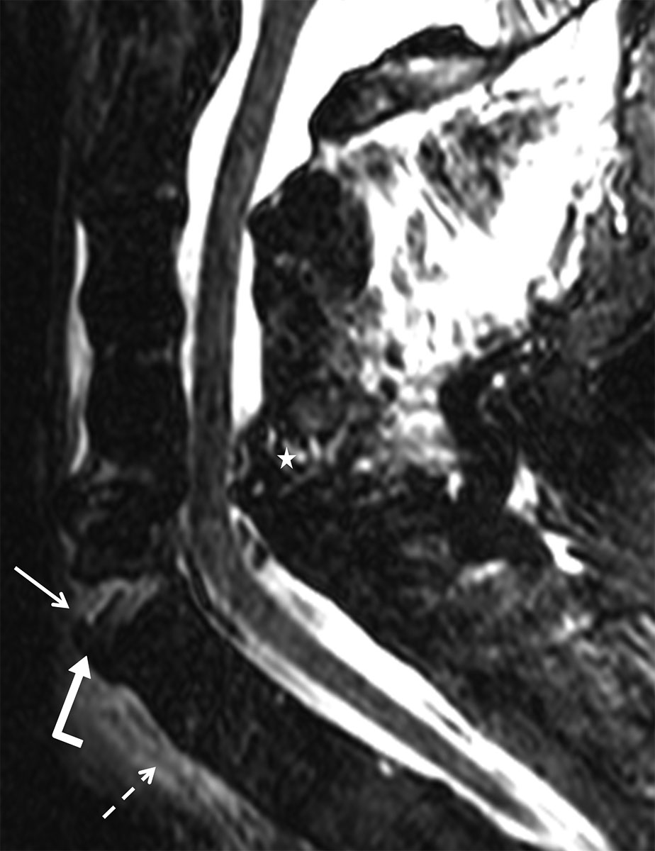
FIG. 11.18 Hyperextension injury.Sagittal TS FSE shows acute hyperextension distraction at C6-C7 with high signal and widening of the anterior disk space (straight arrow) and focal disruption of the ALL (bent arrow). There is prevertebral soft tissue edema (dashed arrow) and injury to the posterior ligamentous complex (star).
In elderly patients, transient retrolisthesis of the vertebral body in hyperextension injuries can further compromise a spinal canal that is already narrowed due to degenerative changes. As a result, the spinal cord may be injured, presenting clinically with a central cord syndrome that is characterized by upper extremity weakness exceeding the degree of lower extremity weakness.
Extension teardrop injury is typically seen in the elderly population after sustaining a fall. The ALL will avulse a small fleck of bone from the anteroinferior aspect of the vertebral body, typically C2 (Fig. 11.19). Like the clay shoveler’s fracture, this is an osseous and not a ligamentous failure. There may be little to no prevertebral soft tissue swelling or hematoma. This fracture is thought to be stable in flexion and unstable in extension.
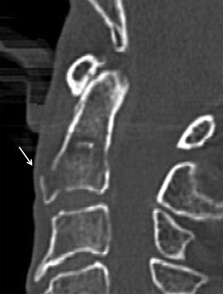
FIG. 11.19 Extension teardrop fracture.Sagittal reformatted CT shows fractured triangular fragment (arrow) rising from the anteroinferior C2 vertebral body. Note the lack of significant prevertebral soft tissue swelling as is typical of this injury.
Tips for Assessing MRI of Spinal Trauma
In the setting of trauma, parenchymal injury to the spinal cord manifests as edema, swelling, and/or hemorrhage. Edema is seen as a longitudinal flame-shaped region of abnormally increased T2 signal. The amount of cord edema will vary with the type of injury, and the initial neurologic deficit has been shown to be proportional to the length of cord edema (18).
One of the most important findings in the traumatized cord is the presence of hemorrhage as this portends a poor neurologic prognosis. Blood products are seen at the point of maximal mechanical impact and are usually centered in the central gray matter. Acutely, blood (in the deoxyhemoglobin state) is hypointense on T2-weighted images, iso- to hypointense on T1-weighted images, and hypointense with blooming on gradient-echo images. Blood will become hyperintense on T1-weighted images when it converts to methemoglobin after 3 or more days, but the conversion process may be delayed due to alterations in the local environment in the setting of injury (1).
Ligaments form the structural scaffolding that play a major role in maintaining the stability of the cervical spine, and MRI is uniquely able to evaluate ligamentous integrity. The ALL, PLL, LF, and interspinous and supraspinous ligaments may be identified on MRI and appear hypointense on T2-weighted images. These ligaments may be disrupted, as demonstrated by areas of focal discontinuity or separation from the underlying periosteum (see Fig. 11.15). Diffusely increased T2 signal, consistent with edema, within the ligament and surrounding muscles can also be seen. These findings are indicative of strain.
The ALL runs longitudinally along the anterior margin of the vertebral bodies and merges with Sharpey fibers at the endplate. In hyperextension injury, the ALL may tear or may avulse a small bone fragment from the anterior vertebral body (see Fig. 11.18). Fluid may undermine the ALL, and focal discontinuity can be seen at the fluid ligament interface.
The PLL runs longitudinally along the posterior margin of the vertebral bodies and may be difficult to visualize as it blends with the ventral dura and annulus on sagittal images. In hyperflexion or significant hyperextension injury, focal tearing or strain of the PLL may be seen. Traumatic disk herniation may also posteriorly displace the PLL with or without tearing.
The LF is readily visualized as a T2 dark band joining adjacent lamina and forms the principal component of the posterior column. Distractive injuries of the posterior elements may cause disruption of the LF and will be visualized as focal discontinuity on parasagittal images (see Fig. 11.15).
In addition to the LF, the interspinous complex is responsible for maintaining stability of the posterior column. High signal on sagittal fat-suppressed T2 sequences will show edema between the spinous processes in the interspinous ligaments or along the posterior margin of the spinous processes in the supraspinous ligament. Focal discontinuity of the interspinous and supraspinous ligaments is observed with severe injuries; however, the implications regarding stability are not clear.
Traumatic disk herniation may occur anywhere in the cervical spine but is most common from C4 to C7. Disk material will extend posteriorly into the epidural space and may compress the cord. Epidural hematoma may occur due to tearing of the epidural venous plexus with extravasation of blood into the ventral epidural space. A collection in this region may deform or have mass effect on the cord (Fig. 11.20). Hyperacute hemorrhage (in the oxyhemoglobin state) may prove difficult to visualize without comparing multiple pulse sequences due to isointensity to spinal cord on T1-weighted sequences and isointensity to CSF on T2-weighted sequences. In the traumatic setting, epidural hemorrhage is more often seen ventrally but can occur dorsally as well.
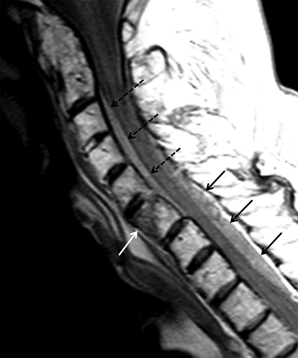
FIG. 11.20 Epidural hematoma.Sagittal proton density (PD) shows a fracture of the C6 vertebral body (white arrow). There is hyperintense signal in the ventral (dashed black arrows) and dorsal (solid black arrows) epidural spaces representing epidural hemorrhage. There is also mild cord compression.
Fractures are best evaluated on CT and may be hard to visualize on MRI, especially those involving the posterior elements or craniocervical junction. Fractures can be identified as hypointense linear areas of low T1 signal with corresponding areas of T2 hyperintensity. MRI may show compressive injury in vertebral bodies as areas of low T1 marrow signal and high T2 marrow signal, even without CT evidence of cortical endplate depression.
Thoracolumbar Injuries
F. Denis introduced the three-column theory in relation to thoracolumbar fractures, which is still the most widely used system for determining spinal instability (2,3). This model divides the spine into three distinct anatomical zones: (a) the anterior column, composed of the ALL, anterior two-thirds of the vertebral body, and annulus fibrosus; (b) the middle column, composed of the posterior one-third of the vertebral body and annulus fibrosus, as well as the PLL; and (c) the posterior column, composed of the posterior elements (pedicles, laminae, facets, spinous processes) and associated LF, as well as interspinous and supraspinous ligaments. According to Denis, a spinal segment is mechanically unstable when structures within more than one column are disrupted.
Thoracolumbar fracture classification
Although most injuries result from a combination of forces, usually one force predominates to result in a main pattern of injury. Furthermore, force vectors applied to certain areas of the spine result in expected patterns of injury (19). Denis classified the most common major fracture patterns as follows: hyperflexion compression, burst, flexion–distraction (Chance-type fractures), and fracture dislocation. Minor injuries, accounting for more than 15% of thoracolumbar fractures, include isolated fractures of the transverse processes, spinous processes, facets, and partes interarticulares. These minor fractures are considered mechanically stable and rarely result in significant neurologic impairment.
Hyperflexion compression
The axis of flexion of the thoracolumbar spine occurs through the midportion of the nucleus pulposus, which is closer to the anterior vertebral body than the posterior vertebral body (20). Given normal kyphotic curvature of the thoracic spine, compressive forces result in more anterior injury, producing typical anterior wedge compression fractures (20) (Fig. 11.21). Accounting for nearly half of all thoracolumbar fractures, compression fractures are typically associated with osteoporosis in the elderly and with high-speed trauma. Fractures may occur at multiple levels and may be contiguous or noncontiguous. At times, compression may be accompanied by lateral flexion or slight rotation, leading to a fracture at the lateral margin of the vertebral body. Compression fractures are generally mechanically stable given disruption of the anterior column alone, although progressive loss of height may result in involvement of the other columns. Distinguishing a compression fracture from other causes of vertebral collapse is at times difficult. Physiologic anterior wedging of approximately 2 mm involves both superior and inferior endplates of several contiguous vertebral bodies and is uniform, accounting for the natural kyphotic curvature of the thoracic spine. Scheuermann disease, or vertebral epiphysitis, typically affects adolescent males and also involves both the superior and inferior endplates (Fig. 11.22A). However, compared with physiologic anterior wedging, the endplates are more irregular and at least three contiguous vertebral bodies are involved. Furthermore, eosinophilic granuloma, a form of Langerhans cell histiocytosis, is the most common cause of vertebra plana (pancake vertebra) in children, mostly occurring in the thoracic spine (Fig. 11.22B).
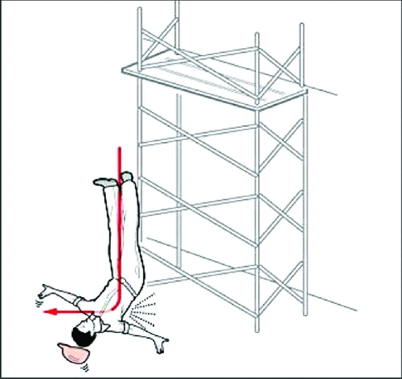
FIG. 11.21 Hyperflexion compression. In a fall from a height, the normal kyphosis of the thoracic spine causes anterior vertebral body wedge compression when subjected to an axial load mechanism. (From Koulouris G, Ting AYI, Morrison WB. Imaging of thoracolumbar spinal injury. In: Schwartz E, Flanders AE. Spinal Trauma: Imaging, Diagnosis, and Management. Philadelphia, PA: Lippincott Williams & Wilkins; 2006:157–187.)
Related posts:
Stay updated, free articles. Join our Telegram channel

Full access? Get Clinical Tree


